


BEFORE YOU BEGIN:
1. Look at the wall or ceiling above the garage door. The door/header
bracket must be securely fastened to structural supports.
2. Do you have a finished ceiling in your garage? If so, a support bracket
and additional fastening hardware (not supplied) may be required.
3. Depending on your door's construction, you might need a special door
arm. See your dealer.
4. Do you have an access door in addition to the garage door? If not,
Model 1702EML Outside Quick Release Accessory is required.
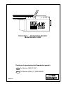
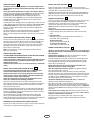
COMPLETED INSTALLATION
As you proceed with the assembly, installation and adjustment
proceedures in this manual, you may find it helpful to refer back to
this illustration of a completed installation.
(1) Rail Brackets (7) Light Lens
(2) Trolley (8) Manual Release Rope & Handle
(3) Rail (9) Curved Door Arm
(4) Hanging Bracket (10) Straight Door Arm
(5) Power Cord (11) Door/Header Brackets
(6) Opener (12) Trolley Release Arm
ASSEMBLY SECTION
-
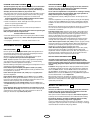
ASSEMBLE THE RAIL
1. (Illustration 5A) Turn the opened rail carton upside down, emptying its
contents onto a level work surface.
2. Unfold the rails, taking care to avoid kinking the screw rod joints.
3. (Illustration 5B) Rotate the rail sections so that the flat side is down and
the screw side is up for all three lengths. Keep it clean and free of debris
while you are working.
CAUTION: During assembly, avoid pulling the rail section housing the
trolley rack (1) away from the screw rod. The rack is factory set about
230mm (9") from the end of the screw rod to the center of the rack.
If the plastic liner slides part way out during assembly, simply push it back in.
4. (Illustration 5C) Beginning with the sprocket end (2), straighten the two
rail sections so that the screw rod is in a straight line at the joint. (Avoid
handling the joints, which may have sharp edges.)
5. Carefully slide the pins (3) at the top edge of the rail into the openings
(4) on the adjacent rail. It is essential that the rail assembly be on a
level surface to achieve proper alignment and to avoid damage to
the pins.
6. Insert two bolts (5) through the center holes of a brace (6), and place its
open length against the rail at this joint, aligning the holes as shown.
Position another brace on the opposite side of the rail over the bolts, add
lock nuts (7), and hand tighten. Insert two additional bolts and hand
tighten.
7. Keeping the rail straight and on a level surface, grasp the screw rods on
each side of the remaining joint and pivot into a straight line. Repeat
steps 5 and 6.
8. With an 11mm wrench, tighten bolts til snug. Work from the center holes
to those further from the joints. Do not overtighten.
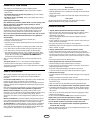
FASTEN THE RAIL TO THE OPENER
Align the rail assembly (1) with the opener (2). Slip the coupling (3) over
the rail sprocket (4). Slide the rail through the opener bracket (5) until the
coupling fits securely over the opener sprocket (6). Align the two screw
holes in the rail with those in the opener bracket. Insert two hex screws (7)
and lock nuts (8). Tighten securely.
INSTALL THE TROLLEY
Slide the trolley (1) onto and along the bottom of the rail until it snaps firmly
in place. Be certain to install it facing correctly: the trolley release arm
must be horizontal (lock position), with its arrow pointed away from
the opener.
ATTACH THE RAIL BRACKETS
Align rail brackets (1) with end of rail assembly. Insert two hex screws (2)
and lock nuts (3). Tighten securely.
ASSEMBLY OF YOUR OPENER IS NOW COMPLETE.
INSTALLATION SECTION
-
Wear protective goggles when working overhead to protect your eyes
from injury.
Disengage all existing garage door locks to avoid damage to the
garage door.
To avoid serious personal injury from entanglement, remove all ropes
connected to the garage door before installing the opener.
Installation of this product shall comply with ZH1/494, VDE 0700 Part 238,
and VDE 0700 Part 1.
It is recommended that the opener be installed 2,1m (7 feet) or more above
the floor where space permits.
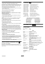
POSITION THE HEADER BRACKET
The header bracket must be rigidly fastened to a structural support of
the garage. Reinforce the wall or ceiling with a 40mm (1-1/2") board if
necessary. Failure to comply may result in improper operation of
safety reverse system.
You can attach the header bracket either to the header wall (1) or to the
ceiling (3). Follow the instructions which will work best for your particular
requirements.
With the door closed, mark the vertical centerline (2) of the garage door.
Extend line onto header wall above the door.
Open door to highest point of travel. Draw an intersecting horizontal line on
header wall 75mm (3") above high point to provide travel clearance for top
edge of door.
INSTALL THE HEADER BRACKET
A. Wall Mount: Center the bracket (2) on the vertical guideline (1) with the
bottom edge of the bracket on the horizontal line (6) (with the arrow
pointing toward the ceiling).
Mark either set of bracket holes (4 or 5). Do not use the holes
designated for ceiling mount. Drill 4,5mm (3/16") pilot holes and fasten
the bracket with wood screws (3).
B. Ceiling Mount: Extend vertical guideline (1) onto the ceiling. Center the
bracket (2) on the vertical mark no more than 150mm (6") from the wall.
Make sure the arrow is pointing toward the wall.
Mark holes designated for ceiling mount only (4). Drill 4,5mm (3/16") pilot
holes and fasten the bracket with wood screws (3). For concrete ceiling
mount, use concrete anchors (7) provided.
ATTACH RAIL TO HEADER BRACKET
Position opener on garage floor below the header bracket. Use packing
material to protect the cover.
Note: To enable the rail to clear sectional door springs, it may be
necessary to lift opener onto a temporary support.
The opener must either be secured to a support or held firmly in place by
another person.
Raise rail until rail brackets and header bracket come together. Join with
clevis pin (1). Insert ring fastener (2) to secure.
POSITION THE OPENER
Note: A 25mm (1") board (1) is convenient for setting an ideal door-to-rail
distance (unless headroom is not sufficient).
Raise the opener onto a stepladder. Open garage door. Place a 25mm
(1") board (1) laid flat on the top section of door near the centerline as
shown. Rest the rail on the board.
If the raised door hits the trolley, pull down on the trolley release arm to
disconnect the inner and outer trolley sections. The trolley can remain
disconnected until connecting door arm to trolley is completed.
12
11
10
9
189
8
7
6
5
85
4
2-GB
114A2421D