


3-en
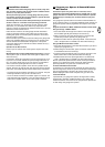
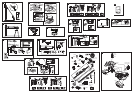
Fasten Door Bracket
If you have a canopy garage door, a door arm conversion kit is required.
Follow the installation instructions included with the replacement door
arm. Exercise care in removing and assembling arm conversion kit. Keep
fingers away from the sliding parts.
NOTE: Horizontal and vertical reinforcement is needed for lightweight
garage doors.
Sectional and One-Piece Door Installation Procedure:
Door bracket (1) has left and right side fastening holes. If your
installation requires top and bottom fastening holes use both the door
bracket and door bracket plate (2) as shown.
1. Center door bracket (with or without door bracket plate, as required)
at the top inside face of door as shown. Mark holes.
A.Standard Sectional or One-piece doors: locate bracket at
inside face of the door.
B. Sectional doors with two horizontal roller channels: 150 -
250mm below the top of the door.
2. A. Wooden doors
Drill 8mm holes (5/16") and fasten the door bracket with nut,
lock washer, and carriage bolt (3).
B. Sheet metal doors
Fasten with wood screws (4).
C. One-piece door optional
Fasten with wood screws (4).
19
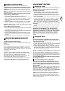
Assemble Door Arm
A. ONE-PIECE DOOR INSTALLATION:
Fasten the straight (1) and curved (2) door arm sections together to
the longest possible length (with a 2 or 3 hole overlap) using hardware
(3,4 and 5). With the door closed connect the straight door arm section
(1) to the door bracket with clevis pin (6). Secure with ring fastener (7).
Disconnect the inner and outer trolley. Slide the outer trolley back
toward the opener and join the curved arm (2) to the connector hole in
the trolley (8) with clevis pin (6). It may be necessary to lift the door
slightly to make the connection. Secure with ring fastener (7).
NOTE: When setting the up limit, the door should not have a
“backward” slant when fully open. A slight backward slant (9) will
cause unnecessary bucking and/or jerking operation as the door is
bing opened or closed from the fully open position.
B. SECTIONAL DOOR INSTALLATION:
Connect according to Figure B, then proceed to Step 21.
20
Attach Rail to Header Bracket
Position opener on garage floor below the header bracket. Use
packing material to protect the cover. Raise rail until holes in the
header sleeve and holes in the header bracket align. Join with clevis
pin (1). Insert ring fastener (2) to secure.
NOTE: To enable the rail to clear sectional door springs, it may be
necessary to lift opener onto a temporary support. The opener must
either be secured to a support or held firmly in place by another
person.
14
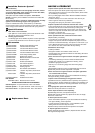
Position the Opener
NOTE: A 25mm (1") board (1) is convenient for setting an ideal
door-to-rail distance (unless headroom is not sufficient).
Raise the opener onto a stepladder. Open garage door. Place a 25mm
(1") board (1) laid flat on the top section of door near the centerline as
shown. Rest the rail on the board.
If the raised door hits the trolley, pull down on the trolley release arm
to disconnect the inner and outer trolley sections. The trolley can
remain disconnected until connecting door arm to trolley is completed.
15
Hang the Opener
The opener must be securely fastened to a structural support of
the garage.
Three representative installations are shown. Yours may be different.
Hanging brackets (1) should be angled (Figure A) to provide rigid
support. On finished ceilings, (Figure B) attach a sturdy metal bracket
(not supplied) (4) to a structural support before installing the opener.
For concrete ceiling mount, (Figure C), use concrete anchors (5)
provided.
On each side of opener measure the distance from the opener to the
structural support (or ceiling).
Cut both pieces of the hanging bracket to required lengths. Flatten one
end of each bracket and bend or twist to fit the fastening angles. Do
not bend at the bracket holes. Drill 4,5mm (3/16") pilot holes in the
structural supports (or ceiling). Attach brackets to supports with wood
screws (2).
Lift opener and fasten to hanging brackets with screw, lock washer
and nut (3). Check to make sure rail is centered over the door.
REMOVE 25mm (1") board. Operate door manually. If door hits the
rail, raise header bracket. Use rail grease and lubricate bottom surface
of rail (6).
16
Attach Emergency Release Rope & Handle
Thread one end of rope (1) through hole in top of red handle so
"NOTICE" reads right side up as shown (3). Secure with an overhand
knot (2). Knot should be at least 25mm (1") from end of the rope to
prevent slipping.
Thread other end of rope through hole in release arm of the outer
trolley (4). Adjust rope length so that handle is 1,8m (6 feet) above the
floor. Secure with an overhand knot.
NOTE: If it is necessary to cut rope, heat seal cut end with a match or
lighter to prevent fraying.
17
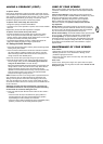
Connect Electric Power
TO AVOID INSTALLATION DIFFICULTIES, DO NOT RUN THE
GARAGE DOOR OPENER UNTIL INSTRUCTED TO DO SO.
Connect the door opener only to an outlet controlled by a double
pole switch.
Install Light
Gently pull lens (2) downward until the lens hinge is in the fully open
position. Do not remove the lens. Install a 24V/21W maximum light
bulb (1) in the socket as shown. The light will turn on and remain lit for
2-1/2 minutes when power is connected. After 2-1/2 minutes it will turn
off. Reverse the procedure to close the lens.
18
Position the Header Bracket
The header bracket must be rigidly fastened to a structural
support of the garage. Reinforce the wall or ceiling with a 50 mm
(1-1/2") board if necessary. Failure to comply may result in
improper operation of safety reverse system.
You can attach the header bracket either to the header wall (1) or to
the ceiling (3). Follow the instructions which will work best for your
particular requirements.
With the door closed, mark the vertical centerline (2) of the garage
door. Extend line onto header wall above the door.
Open door to highest point of travel. Draw an intersecting horizontal
line (4) on header wall 5 cm (2") above high point to provide travel
clearance for top edge of door.
12
Install the Header Bracket
NOTE: Refer to vertical center and horizontal lines created in step
12 for proper placement of header bracket.
A. Wall Mount: Center the header bracket (1) on the vertical center
line (2) with the bottom edge of the header bracket on the
horizontal line (4) (with the arrow pointing toward the ceiling). Mark
all of the header bracket holes (5). Drill 4,5 mm (3/16") pilot holes
and fasten the header bracket with wood screws (3).
B. Ceiling Mount: Extend vertical center line (2) onto the ceiling.
Center the header bracket (1) on the vertical mark no more than
150 mm (6") from the wall. Make sure the arrow is pointing toward
the opener. Mark all of the header bracket holes (5). Drill 4,5 mm
(3/16") pilot holes and fasten the header bracket with wood screws
(3). For concrete ceiling mount, use concrete anchors (6) provided.
13