


16
Inside
Garage
Wall
“C” Shaped
Wrap
Mounting Bracket
with Square Holes
1/4-20x1/2"
Carriage Bolts
1/4"-20 Lock Nuts
Drill 3/8"
Holes
Garage
Door Track
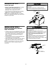
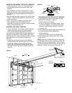
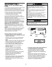
Figure 3 Garage DOOR Track Installation
Mounting Bracket
With Square Holes
#10-32x3/8"
Screws
“C” Wrap
#10-32
Lock Nuts
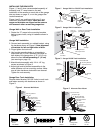
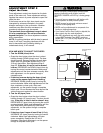
Figure 1 Garage WALL or DOOR Track Installation
Mounting Bracket
with Slot
1/4"-20
Lock Nuts
1/4x1-1/2"
Lag Screws
1/4-20x1/2" Carriage Bolts
(with square shoulder)
Inside
Garage
Wall
“C” Wrap
Mounting Bracket
with Square Holes
Figure 2 Garage WALL Installation
Lag Screw 1/4x1-1/2"
Screw
#10-32x3/8"
Lock Nut
1/4"-20
Lock Nut
#10x32
Staples
Carriage Bolts
1/4"-20x1/2"
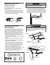
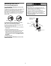
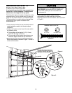
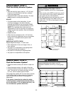
HARDWARE SHOWN ACTUAL SIZE
Figure 4 Alternate Wall Mount
“C” Wrap
Inside
Garage
Wall
Mounting Bracket
with Square Holes
Mounting Bracket
with Slot
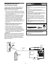
Sensor
with wire
Indicator Light
Garage
Floor
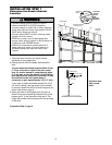
INSTALLING THE BRACKETS
Figure 1, 2 and 3 show recommended assembly of
bracket(s) and “C” wrap based on the wall
installation of the sensors on each side of the garage
door as shown on page 15, or on the garage door
tracks themselves.
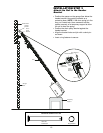
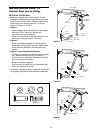
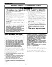
Figure 4 and 5 are variations which may fit your
installation requirements better. Make sure the
wraps and brackets are aligned so the sensors
will face each other across the garage door.
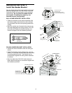
Garage Wall or Door Track Installation
1. Fasten the “C” wraps to the mounting brackets
having square holes, using th hardware shown in
Figure 1.
Garage Wall Installation
2. Connect each assembly to a slotted bracket, using
the hardware shown on Figure 2. Note alignment
of brackets for left and right sides of door.
3. Finger tighten the lock nuts.
4. Use bracket mounting holes as a template to
locate and drill (2) 3/16" diameter pilot holes on
both sides of the garage door, 4"-6" (10-15 cm)
above the floor but not exceeding 6" (15 cm)
(see warning on page 15).
5. Attach bracket assembly with 1/4"x1-1/2" lag
screws as shown in Figure 2.
6. Adjust right and left bracket assemblies to the
same distance out from mounting surface. Make
sure all door hardware obstructions are cleared.
Tighten the nuts securely.
Garage Door Track Installation
Discard slotted bracket. Drill 3/8" holes in each track
and fasten securely with hardware as shown in
Figure 3.
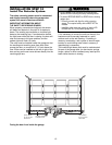
Garage
Floor
Indicator Light
Inside
Garage
Wall
Mounting Bracket
with Slot
Attach with
concrete
anchors
(not provided)
Mounting Bracket
with Square Holes
“C” Wrap
Sensor with wire
Figure 5 Alternate Floor Mount