


CLOSE
EDGE
R93
L1
K2
OPEN EDGE/
OPEN
PHOTO
CLOSE
PHOTO
Z22
P1
F2
MOV1
D1
Q12
U4
CONTROL
INPUTS
FORCE
TIMER TO
CLOSE
OFF MAX
OPEN
SINGLE BUTTON
RESET
STOP
SHADOW
INTERRUPT
CHGR
OVLD
COM
COM
CTRL
LOOP
INPUTS
D129
Z4
U3
D2
D44
C11
C13
C12
K1
F3
K3
K4
R196
F7
CTRL
OVLD
TIMER
RUNNIN G
GATE 2
SET
OPEN
LIMIT
SET
CLOSE
LIMIT
LEARN
LIMITS
DIAGNOSTIC
GATE 1
LEARN
XMITTER
LOCK /
ON OFF
PWR
C69
OFF MAX
J2
Ø
PWR
SINGLE BUTTON
AC PWR
/SOLAR
D8
D4
R9
R329
R27
MOV2
R4
C2
BIPART DELAY
F12
Q9
Q6
Q1
J19
CESSORY
0VLD
C75
C73
C72
C71
C7
Ø
C66 C65
C68
C33
F11
R186
R42
Ø
R423
J24 J23 3
Ø
A 32V
30
C64
R22
U2
J18
K6
JU1
JU1
JU2
DB1
R184
CLOSE
PHOTO
OPEN
PHOTO
CLOSE
Z8
GE/
DGE/
Open
Safety
Sensors
OPEN EDGE/
PHOTO
CLOSE
Z9
Entrapment
Safety
Sensors
Close Safety Sensors
Black
striped
wires
Black
striped
wires
Black
Black
Black
striped
wires
Red
Red
Black
Black
Red
Red
Black
Black
Red
Red
YEL
T ALARM
JU1
R6
SWITCHIR
++
__
GRN
BRN
WHT
RED
BLU
SWITCHIR
++
__
Entrapment/Open
Safety Sensors
Black
striped
wires
Red
wires
Black
Striped Wire
Black
Striped Wire
Red
Red
Close
Safety Sensors
Red
Lead
Wire
Black
Striped
Lead
Wire
Indicator Light
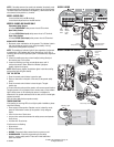
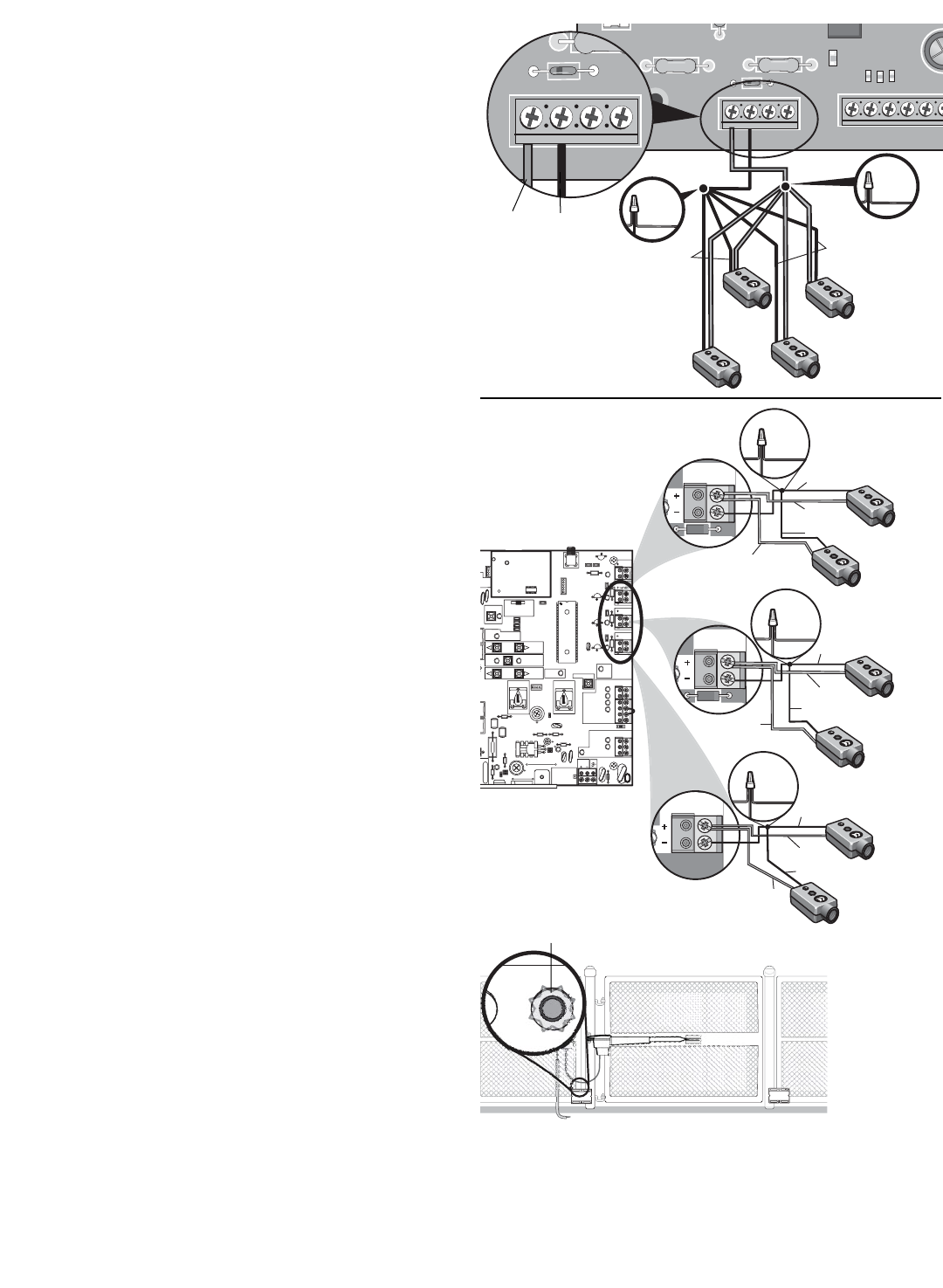
MODEL GA200D
MODEL GA400D AND GA420D
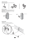
NOTE: If the safety sensor wires need to be extended, the polarity must
be maintained when connecting the safety sensors to the control board.
The black striped wire connects to the negative (-) terminal and the red
wire connects to the positive (+) terminal.
MODEL GA200D ONLY
• Insert red lead wire into IR+ terminal.
• Insert black striped lead wire into IR- terminal.
MODELS GA400D AND GA420D ONLY
Entrapment Safety Sensors
• Connect ENTRAPMENT safety sensor wires to P8 terminal.
Open Safety Sensors
• Connect OPEN (Photo Input) safety sensor wires to P7 terminal.
Close Safety Sensors
• Connect CLOSE (Photo Input) safety sensor wires to P9 terminal.
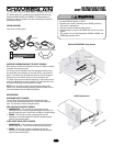
ALIGN SAFETY SENSORS
1. Reconnect power and batteries to the operator. The indicator lights in
both the sending and receiving eyes will glow steadily if wiring
connections and alignment are correct.
NOTE: The sending eye indicator light will glow regardless of alignment
or obstruction. If the indicator light in the receiving eye is off, dim, or
flickering (and the invisible light beam path is not obstructed), alignment
is required.
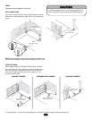
2. Loosen the sending eye wing nut and readjust, aiming directly at
the receiving eye. Lock in place.
3. Loosen the receiving eye wing nut and adjust sensor until it
receives the sender’s beam. When the indicator light glows
steadily, tighten the wing nut.
NOTE: When properly aligned, the indicator lights in both the sending
and receiving eyes will glow steadily.
TEST THE SYSTEM
1. Press the remote control button to open the gate.
2. Place an obstruction in the path of the close or entrapment safety
sensor.
3. Press the remote control button to close the gate. The gate
should stop.
4. Remove the obstruction and the operator will resume normal function.
The gate operator will not function from a remote control if the indicator
light in either sensor is off indicating the sensor is misaligned or
obstructed. If the system continues to fail the test, call for a trained gate
systems technician.
Verify all other safety devices operate correctly.
TROUBLESHOOTING
If the sending or receiving LEDs do not light up after installation, please
check the following:
• Power supply to the operator. Operator may be in stand-by mode,
press the reset button to wake up the operator. Verify voltage at
inputs.
• A short in the wires. Check wires.
• Incorrect wire connections between the safety sensors and operator.
Verify wiring.
• A broken wire. Check wires.
If both sensors are flashing:
• Align sensors.
• Remove obstruction.
• GA200D - Disconnect safety sensors then turn power on unit.
• GA400D/GA420D - Erase the programming for the safety
sensors - remove safety sensor. Press learn limits button then
press reset button.
© 2008, The Chamberlain Group, Inc.
01-33959C All Rights Reserved