


ASSEMBLY SECTION
IMPORTANT: If you have a canopy door, you need to use the instructions packed with The Chamberlain
Arm™ Accessory in conjunction with this Owner's Manual when assembling the rail.
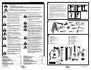
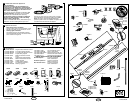
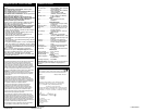
Completed Installation
As you proceed with the assembly, installation and adjustment procedures in this manual, you may find it helpful
to refer back to this illustration of a completed installation.
4
1
2
3
12
4
6
9
8
10
11
13
14
7
15
10
5
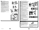
BEFORE YOU BEGIN:
1. Look at the wall or ceiling above the garage door. The header bracket must be securely fastened to structural
supports.
2. Do you have a finished ceiling in your garage? If so, a support bracket and additional fastening hardware (not
supplied) may be required.
3. Depending on your door's construction, you might need a special door arm. See your dealer.
4. Do you have an access door in addition to the garage door? If not, Model 1702E Outside Quick Release
Accessory is required. This accessory allows manual operation of the garage door from outside in case of
power failure.
(1) Header Sleeve
(2) Idler Pulley Bracket
(3) Trolley
(4) Rail
(5) Chain/Belt
(6) Hanging Bracket
(7) Power Cord
(8) Opener
(9) Light Lens
(10) Manual Release
Rope & Handle
(11) Curved Door Arm
(12) Straight Door Arm
(13) Door Bracket
and Plate
(14) Header Bracket
(15) Trolley Release Arm
3-GB
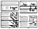
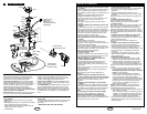
Install the Chain/Belt
Remove chain/belt from carton and lay chain out on
floor (do not allow chain/belt to twist).
A. Chain: Push pins of master link bar (3) through
chain link (4) and hole in back end of trolley (5).
Push cap (2) over pins and onto notches. Slide
clip-on spring (1) over cap and onto pin notches
until both pins are securely locked in place.
B. Belt: Hook the trolley connector (6) into the slot (7)
on the trolley (8).
Insert Chain/Belt into Rail & Assemble
Header Sleeve
Slide pulley bracket (1) and inner trolley (2) into back
(opener end) of rail assembly (3), be sure to insert
pulley bracket as shown with arrow (4) pointing
toward front (header end) of rail (5). Push bracket
toward front (header end ) of rail (5). Insert carriage
bolt (6) through header sleeve bracket (7). Loosely
thread spring nut (8) and flat washer (9) onto carriage
bolt. Insert carriage bolt (6) of header sleeve
assembly (7) into bold cut out in pulley bracket (1).
Slide header sleeve assembly (7) on to front (header
end) of rail (10).
Attach Trolley to Rail
Slide outer trolley (1) into back (opener) end of the rail
assembly (2), be sure end with trolley release arm (3)
is heading in direction of opener. Slide outer trolley
down rail until it engages with inner trolley.
A
1
3
2
4
5
7
B
6
8
4
5
3
1
2
8
7
6
1
6
7
10
9
1
3
2
6
8
114A2910B-GB
7
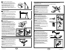
Assemble the Rail
Grease inside edges of rail sections using grease (1).
Place rail pieces (2) on flat surface for assembly. All
four rail sections are interchangeable. Slide rail brace
(3) onto rail section. Connect rail by sliding rail brace
onto next rail section. Tap rail assembly (4) on piece
of wood (5) until rail sections are flush. Repeat with
remaining rail sections.
4
5
2
3
2
1
5
Assemble Header Sleeve
Thread spring nut on carriage bolt until finger tight.
Insert a screwdriver tip (1) into one of the slots of the
nut ring (2) and brace it firmly against the header
sleeve. Place an open end wrench (3) on the square
end of the spring nut (4), slightly rotate nut about 1/4
turn clockwise until nut ring (2) is released against
header sleeve (5). This sets spring to optimum chain
tension. Chain may slip off sprocket if chain/belt is too
loose. If chain does slip re-tighten spring nut by turing
nut clockwise 1/2 turn. Do NOT overtighten
chain/belt.
Fasten Rail to Opener and Install
Chain/Belt
Holding chain (4) and belt (5) out of the way, slide rail
(1) onto shim (2) until rail is secure. Take the
chain/belt and wrap it around the sprocket (3). Make
sure the teeth on the sprocket have engaged the
chain/belt.
1
2
3
4
5
INSTALLATION SECTION
Wear protective goggles when working overhead to protect your eyes from injury.
Disengage all existing garage door locks to avoid damage to the garage door.
To avoid serious personal injury from entanglement, remove all ropes connected to the garage door
before installing the opener.
Installation of this product shall comply with ZH1/494, VDE 0700 Part 238, and VDE 0700 Part 1.
It is recommended that the opener be installed 2,1m (7 feet) or more above the floor where space permits.
1
2
3
4
1
2
3
5
2
1
3
2
1
3
Install the Header Bracket
NOTE: Refer to vertical center and horizontal lines
created in step 12 for proper placement of header
bracket.
A. Wall Mount: Center the header bracket (1) on the
vertical center line (2) with the bottom edge of the
header bracket on the horizontal line (4) (with the
arrow pointing toward the ceiling). Mark all of the
header bracket holes (5). Drill 4,5mm (3/16") pilot
holes and fasten the header bracket with wood
screws (3).
B. Ceiling Mount: Extend vertical center line (2) onto
the ceiling. Center the header bracket (1) on the
vertical mark no more than 150mm (6") from the
wall. Make sure the arrow is pointing toward the
opener. Mark all of the header bracket holes (5). Drill
4,5mm (3/16") pilot holes and fasten the header
bracket with wood screws (3). For concrete ceiling
mount, use concrete anchors provided.
B
150mm
(6")
1
2
3
Attach Sprocket Cover
Place sprocket cover (1) on top of the opener (2),
secure with screws (3).
10
13
5
5
2
50mm
(2")
3
1
4
A
4-GB
114A2910B-GB
9
11
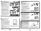
Position the Header Bracket
The header bracket must be rigidly fastened to a
structural support of the garage. Reinforce the wall or
ceiling with a 40mm (1-1/2") board if necessary.
Failure to comply may result in improper operation of
safety reverse system.
You can attach the header bracket either to the header
wall (1) or to the ceiling (3). Follow the instructions which
will work best for your particular requirements. With the
door closed, mark the vertical centerline (2) of the garage
door. Extend line onto header wall above the door.
Open door to highest point of travel. Draw an intersecting
horizontal line (4) on header wall 5 cm (2") above high
point to provide travel clearance for top edge of door.
3
1
2
4
12
Install the Header Bracket
NOTE: Refer to vertical center and horizontal lines
created in step 12 for proper placement of header
bracket.
A. Wall Mount: Center the header bracket (1) on the
vertical center line (2) with the bottom edge of the
header bracket on the horizontal line (4) (with the
arrow pointing toward the ceiling). Mark all of the
header bracket holes (5). Drill 4,5mm (3/16") pilot
holes and fasten the header bracket with wood
screws (3).
B. Ceiling Mount: Extend vertical center line (2) onto
the ceiling. Center the header bracket (1) on the
vertical mark no more than 150mm (6") from the
wall. Make sure the arrow is pointing toward the
opener. Mark all of the header bracket holes (5). Drill
4,5mm (3/16") pilot holes and fasten the header
bracket with wood screws (3). For concrete ceiling
mount, use concrete anchors provided.
B
150mm
(6")
1
2
3
13
5
5
2
50mm
(2")
3
1
4
A