


Failure to comply with the following instructions may result in serious personal injury or
property damage.
• Read these instructions carefully
• The garage door opener is designed and tested to offer reasonable safe service
provided it is installed and operated in strict accordance with the instructions in this
manual.
These safety alert symbols mean Warning – a personal safety or property damage
instruction. Read these instructions carefully.
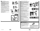
Warning: If your garage has no service entrance door, Model 1702E Outside Quick Release must be installed.
This accessory allows manual operation of the garage door from outside in case of power failure.
Keep garage door balanced. Do not let
the garage door opener compensate for
a binding or sticking garage door.
Sticking or binding doors must be
repaired. Garage doors, door springs,
cables, pulleys, brackets and their
hardware are under extreme tension and
can cause serious personal injury.
Do not attempt to loose, move or
adjust them. Call for garage door
service.
Do not wear rings, watches or loose
clothing while installing or servicing a
garage door opener.
To avoid serious personal injury from
entanglement, remove all ropes
connected to the garage door before
installing the door opener.
Installation and wiring must be in
compliance with your local building and
electrical codes. Connect the power
supply cord only to properly earthed
mains.
Lightweight doors of fiberglass,
aluminum or steel must be
substantially reinforced to avoid door
damage. (See page 6.) The best solution
is to check with your garage door
manufacturer for an opener installation
reinforcement kit.
The safety reverse system test is very
important. Your garage door MUST
reverse on contact with a 40mm obstacle
placed on the floor. Failure to properly
adjust the opener may result in serious
personal injury from a closing garage
door. Repeat the test once a month
and make any needed adjustments.
This unit should not be installed in a
damp or wet space.
Door must not extend over public
byway during operation.
Start by Reading These Important Safety Instructions
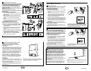
The Protector System must be
installed when the force at the edge of
the closing door force exceeds 400N
(40kg). Excessive force will interfere with
the proper operation of the Safety
Reverse System or damage the
garage door.
Permanently fasten the caution label
adjacent to the wall-mounted door control
control button as a reminder of safe
operating procedures.
Disengage all existing garage door
locks to avoid damage to garage door.
Install the lighted door control button (or
any additional push buttons) in a location
where the garage door is visible, at a
height of at least 1.5m and out of the
reach of children. Do not allow
children to operate push button(s) or
remote control(s). Serious personal
injury from a closing garage door may
result from misuse of the opener.
Activate opener only when the door is
in full view, free of obstructions and
opener is properly adjusted. No one
should enter or leave the garage while
the door is in motion. Do not allow
children to play near the door.
Use manual release only to disengage
the trolley and, if possible, only when the
door is closed. Do not use the red
handle to pull the door open or closed.
Disconnect electric power to the
garage door opener before making
repairs or removing covers.
This product is provided with a power
supply cord of special design which, if
damaged, must be replaced by a power
supply cord of the same type; such a
power supply cord may be obtained and
fitted by a specialist.
CONTENTS PAGE
SAFETY RULES . . . . . . . . . . . . . . . . . . . . . . . . . .1
DOOR TYPES . . . . . . . . . . . . . . . . . . . . . . . . . . . .2
TOOLS REQUIRED . . . . . . . . . . . . . . . . . . . . . . . .2
HARDWARE PROVIDED . . . . . . . . . . . . . . . . . . . .2
BEFORE YOU BEGIN . . . . . . . . . . . . . . . . . . . . . .3
COMPLETED INSTALLATION . . . . . . . . . . . . . . . .3
ASSEMBLY . . . . . . . . . . . . . . . . . . . . . . . . . . . . .3-4
INSTALLATION . . . . . . . . . . . . . . . . . . . . . . . . . .4-5
CONNECT ELECTRIC POWER . . . . . . . . . . . . .6-7
PROGRAMMING THE CODE . . . . . . . . . . . . . . .8-9
ADJUSTMENT . . . . . . . . . . . . . . . . . . . . . . . . . . .10
CONTENTS PAGE
INSTALL THE PROTECTOR
SYSTEM (OPTIONAL) . . . . . . . . . . . . . . . . . . . . .11
SPECIAL FEATURES . . . . . . . . . . . . . . . . . . . . . .11
ACCESSORIES . . . . . . . . . . . . . . . . . . . . . . . . . .11
REPLACEMENT PARTS . . . . . . . . . . . . . . . . .12-13
CARE OF YOUR OPENER . . . . . . . . . . . . . . . . . .13
MAINTENANCE OF YOUR OPENER . . . . . . . . . .13
HAVING A PROBLEM? . . . . . . . . . . . . . . . . . . . . 14
OPERATION OF YOUR OPENER . . . . . . . . . . . .15
SPECIFICATIONS . . . . . . . . . . . . . . . . . . . . . . . .15
1-GB
114A2910B-GB
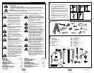
TOOLS REQUIRED
2
114A2910B-GB
2-GB
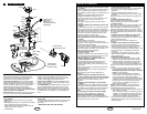
A. One-Piece Door with Horizontal Track Only
B. One-Piece Door with Horizontal and Vertical
Track – Special door arm (E, The
Chamberlain Arm™) and The Protector
System (29 (9)) are required. See your dealer.
C. Sectional Door with Curved Track – See 20B –
connect door arm. The Protector System
(29 (9) is required for doors that are over 2.5m
in height.
D. Canopy door – Special door arm (E, The
Chamberlain Arm™) and The Protector
System (29 (9)) are required. See your dealer
E. The Chamberlain Arm™ for use on door types
B and D.
DOOR TYPES
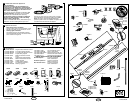
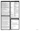
HARDWARE PROVIDED
(1) Hex Bolt (2)
(2) Clevis Pin (1)
(3) 8mm Carriage Bolt (2)
(4) Wood Screws (8)
(5) Sheet Metal Screws (2)
(6) Clevis Pin (2)
(7) Rope
(8) Handle
(9) Insulated Staples (10)
(10) Anchor (2)
(11) Concrete Anchor (6)
(12) Lock Washer (5)
(13) Hex Nut (5)
(14) Ring Fastener (3)
(15) Rail Grease (1)
(16) Lock Nut (1)
(17) Metric Tapping Screw (4)
(18) Hex Screw (3)
(19) Flat Washer (2)
(20) Stop Bolt
A B
ED
C
10
7
9
3
4
5
6
12
13
8
N
O
T
IC
E
11
2
15
14
17
18
1
16
19
20
2
1
11mm, 13mm
11/13mm
10mm, 8mm,
4,5mm, 4mm
1
3