


21
Cut this end
Lock
Washers
5/16"
Nuts
5/16"-18
Bolts
5/16"-18x7/8"
Door Bracket
Ring
Fastener
Door
Bracket
Straight
Door Arm
Curved Door Arm
Inner
Trolley
Outer
Trolley
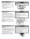
Emergency
Release
Handle
Clevis Pin
5/16"x1"
Clevis Pin
5/16"x1-1/4"
Lock
Washers
5/16"
Nuts
5/16"-18
Bolts
5/16"-18x7/8"
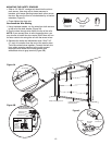
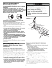
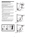
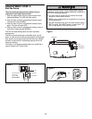
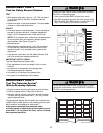
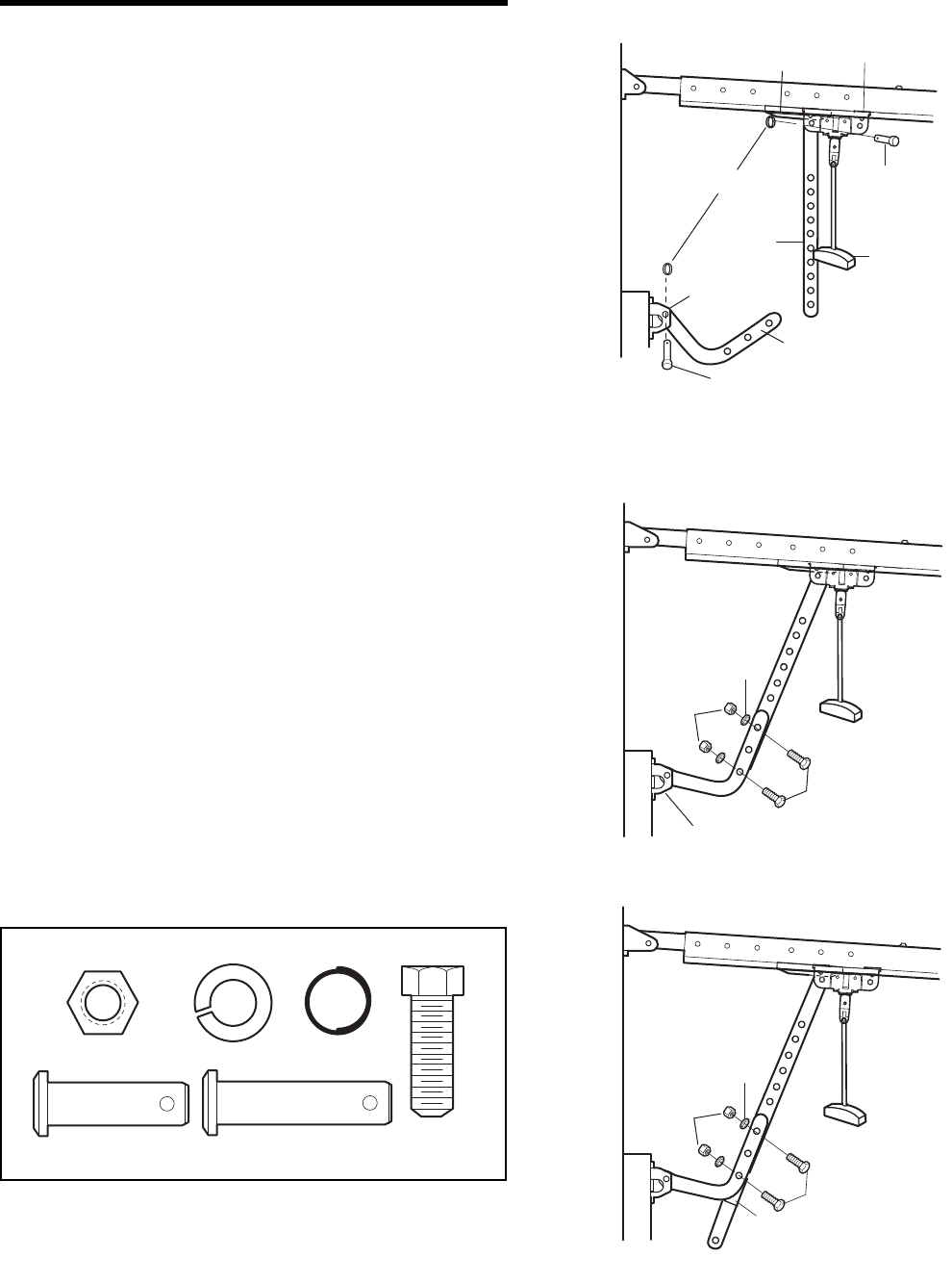
INSTALLATION STEP 14
Connect Door Arm to Trolley
Follow instructions which apply to your door type as
illustrated below and on the following page.
SECTIONAL DOORS ONLY
Make sure garage door is fully closed. Pull the emergency
release handle to disconnect the outer trolley from the
inner trolley. Slide the outer trolley back (away from the
door) about 2" (5 cm) as shown in Figures 1, 2 and 3.
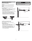
Figure 1:
• Fasten straight door arm section to outer trolley with the
5/16"x1" clevis pin. Secure the connection with a ring
fastener.
• Fasten curved section to the door bracket in the same
way, using the 5/16"x1-1/4" clevis pin.
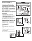
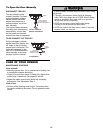
Figure 2:
• Bring arm sections together. Find two pairs of holes that
line up and join sections. Select holes as far apart as
possible to increase door arm rigidity.
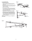
Figure 3, Hole alignment alternative:
• If holes in curved arm are above holes in straight arm,
disconnect straight arm. Cut about 6" (15 cm) from the
solid end. Reconnect to trolley with cut end down as
shown.
• Bring arm sections together.
• Find two pairs of holes that line up and join with bolts,
lock washers and nuts.
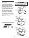
Pull the emergency release handle toward the opener at
a 45° angle so that the trolley release arm is horizontal.
Proceed to Adjustment Step 1, page 23. Trolley will
re-engage automatically when opener is operated.
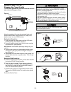
Figure 1
Figure 2
Figure 3
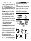
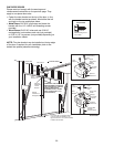
Lock Washer 5/16"
Nut 5/16"-18
Ring Fastener
Hex Bolt
5/16"-18x7/8"
Clevis Pin
5/16"x1" (Trolley)
Clevis Pin
5/16"x1-1/4" (Door Bracket)
HARDWARE SHOWN ACTUAL SIZE