


13
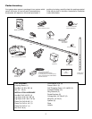
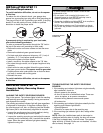
Wing Nut
1/4"-20
Staples
Carriage Bolt
1/4"-20x1/2"
HARDWARE SHOWN ACTUAL SIZE
Carriage Bolt
1/4"-20x1/2"
Bracket
Bell Wire
Lens
Wing Nut
1/4"-20
Wire Clips
Rail
Sensor Wire
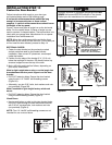
Strip wire 7/16"
7/16" (11 mm)
Grey
White
White/Black
Wire
White Wire
Quick-Connect
Terminals
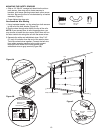
Left Side Panel
Antenna
To release
or insert
wire, push
in tab with
screwdriver tip
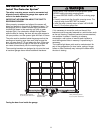
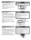
SAFETY REVERSING
SENSORS CONNECTIONS
Invisible Light Beam
Protection Area
Safety Reversing Sensor
Cable
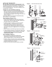
Figure 5A
Figure 5B
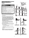
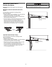
MOUNTING THE SAFETY SENSORS
• Slide a 1/4"-20x1/2" carriage bolt head into the slot on
each sensor. Use wing nuts to fasten sensors to
brackets, with lenses pointing toward each other across
the door. Be sure the lens is not obstructed by a bracket
extension (Figure 5).
• Finger tighten the wing nuts.
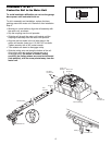
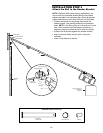
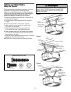
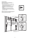
Recommended Wire Routing
1. Using insulated staples, run the wires from both sensors
to the rail at the door header (Figure 5A).
2. Run the wires through wire clips at the top of the rails.
NOTE: If your access door is near the garage door, you
may choose to install the door control at this time and run
the door control wire along the rail with the sensor wires.
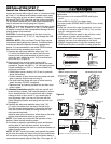
3. Separate the white and white/black wires. Strip 7/16"
(11 mm) of insulation from the end of the sensor wires.
Twist like colored wires together. Connect the bell wire
from safety reversing sensors to the quick-connect
terminals: white wires to the white terminal and
white/black wires to grey terminal (Figure 5B).
Figure 5