


Installation Step 6
Install the Multi-Function
Door Control Panel
14
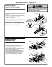
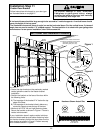
Children operating or playing with a garage
door opener can injure themselves or others.
The garage door could close and cause
serious injury or death.
Install the Door Control (or any additional push
buttons) out of the reach of children and away
from all moving parts of the door and door
hardware,
but where the garage door is visible.
Do not allow children to operate the push
button(s) or the remote control transmitter(s).
A moving garage door could injure someone
under it.
Activate the opener only when the
door is properly adjusted, you can see it clearly,
and there are no obstructions to door travel.
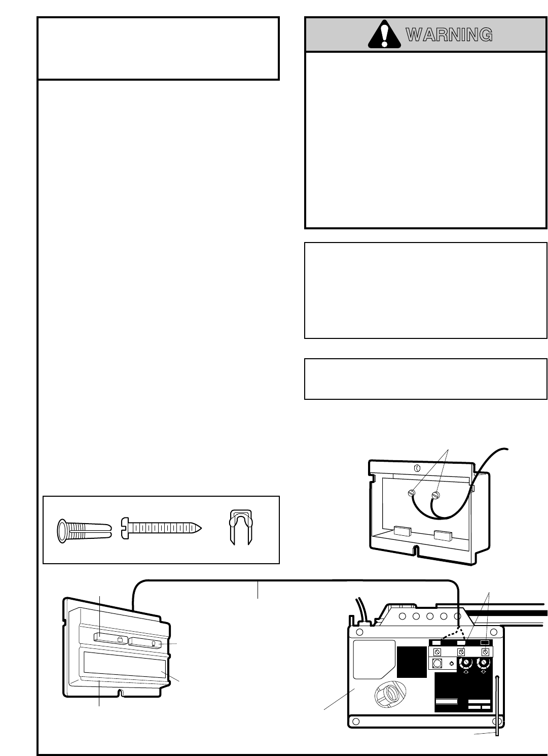
Opener
Terminal
Screws
Antenna
Right Side
Panel of
Opener
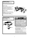
Multi-Function
Door Control Panel
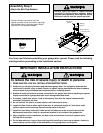
Multi-Function
Door Control Panel
Terminal Screws
WHITE
RED
LIGHT
LOCK
Door
Control
Button
Light Button
Lock Button
- 1
- 2
KG
KG
M.D.C. CERT. NO.
1
3
9
7
5
132C2105-1
PART NO: Nº DE PIÈCE:
D.O.C. CERT. NO.
DATE:
Sears Roebuck & Co.
Sears Canada Inc., Toronto
Assembled in Mexico - Assemblé du Mexique
PAT. #RE29,525; 4,750,201; 4,806,930 Other Patents Pending.
AVERTISSEMENT: Pour réduire les risques de
blessures mortelles par happement, après tout
réglage de la force de déclenchement ou des
seuils de fin de course s'assurer que le sens de
la course s'inverse lorsque la porte entre en
contact avec un object de 13 mm (1 po) de
hauteur (ou un madrier de 2 x 4 de section, à
plat) posé sur le sol. Effectuer les reglages
selon les procédures décrites dans la notice.
1
3
9
7
5
2 3
1
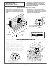
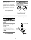
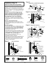
2-Conductor
Bell Wire
• Strip 1/4" of insulation from one end of the bell
wire; connect the wire to the two screw terminals
on the back of the Door Control by color:
white to 2 and white/red to 1.
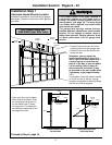
• Locate the Door Control within sight of the
door at a minimum height of 5 feet where small
children cannot reach, and away from all
moving parts of the door and door hardware.
Fasten the Multi-Function Door Control Panel
securely with 6ABx1" screws. If installing into
drywall, drill 5/32" holes and use the anchors
provided.
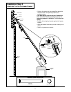
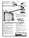
• Run the bell wire up the wall and across the ceiling
to the opener. Use insulated staples to secure the
wire in several places. Be careful not to pierce the
wire with a staple, thereby resulting in a short.
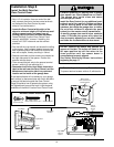
• Receiver terminals and the antenna are located on
the right side panel of the opener. Position the
antenna wire as shown.
• Then connect the bell wire to the opener terminal
screws: white to 2 and white/red to 1.
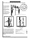
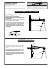
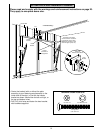
• Remember to affix the User Safety Instruction
label to the wall near the Door Control, and the
Maintenance Instruction label in a prominent
location on the inside of the garage door.
If the label adhesive will not adhere to your garage
wall surface (or becomes loose with time) use tacks
to secure the label alongside the Door Control.
Page 28 explains how to operate the opener using
the lighted push bar and the Lock & Light features
available on the Multi-Function Door Control Panel.
Do NOT connect the power and operate the
opener at this time.
The trolley will travel to the
full
open
position but will not return to the
close
position until the sensor beam is
connected and properly aligned.
See Safety Reversing Sensor Instructions
beginning on page 17.
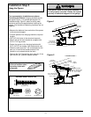
Dry Wall Anchors
Insulated Staples
6ABx1" Screw
Multi-Function Door Control
Hardware Shown Actual Size
Outside Keylock Accessory Connections
To opener terminal screws: white to 2; white/red to 1
WARNING