


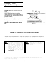
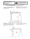
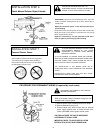
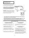
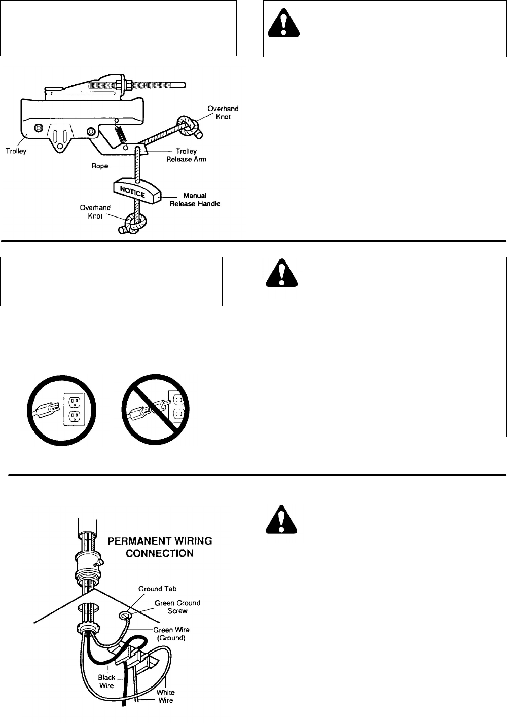
INSTALLATION STEP 6
Attach Manual Release Rope & Handle
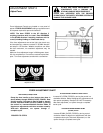
USE MANUAL RELEASE ROPE ONLY TO
DISENGAGE TROLLEY. DO NOT USE ROPE AND
HANDLE TO PULL DOOR OPEN OR CLOSED.
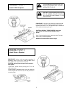
PROCEDURE: Thread one end of rope through hole in top of red
handle so 'NOTICE' reads right side up as shown. Secure with an
overhand knot.
NOTE: Knot should be at least 1" from the end of the rope to
prevent slipping.
Thread other end of rope through hole in release arm of outer trolley.
Adjust rope length so that handle is 6 feet above the floor. Secure
with an overhand knot as above.
NOTE: If it is necessary to cut rope, heat seal cut end with a
match or lighter to prevent fraying and/or raveling.
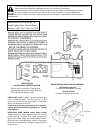
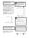
INSTALLATION STEP 7
Connect Electric Power
TO AVOID SERIOUS PERSONAL INJURY FROM
ENTANGLEMENT, REMOVE ALL THE ROPES
CONNECTED TO GARAGE DOOR BEFORE
OPERATING OPENER.
TO AVOID DAMAGE TO GARAGE DOOR AND OPENER,
MAKE DOOR LOCKS INOPERATIVE BEFORE CONNECTING
ELECTRIC POWER. USE A WOOD SCREW OR NAIL TO
HOLD LOCKS IN "OPEN" /UNLOCKED) POSITION.
THE INSTALLATION & THE WIRING MUST BE IN
COMPLIANCE WITH LOCAL ELECTRICAL AND BUILDING
CODES.
OPERATION AT OTHER THAN 120V 60Hz WILL CAUSE
OPENER MALFUNCTION AND DAMAGE.
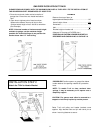
Opener MUST be permanently wired or plugged into
a grounded 3-prong receptacle wired according to
local electrical codes. DO NOT use a 2-wire adapter.
DO NOT USE an extension cord.
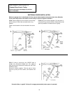
RIGHT
WRONG
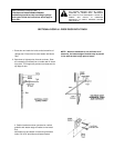
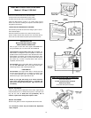
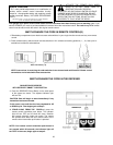
PROCEDURE FOR PERMANENT WIRING (if required by local codes)
DISCONNECT THE POWER AT THE FUSE BOX
BEFORE PROCEEDING.
Refer to illustration. Make connection through the 7/8"
diameter hole in top of opener.
1. Remove opener cover screws and set cover aside.
2. Remove attached 3-prong cord.
3. Connect black (line) wire to black wire on terminal
block; white (neutral) wire to white terminal wire;
Green (GROUND) wire to green around screw.
CAUTION: BE SURE THE UNIT IS GROUNDED
ACCORDING TO LOCAL CODE.
IMPORTANT NOTE: TO AVOID INSTALLATION
DIFFICULTIES, DO NOT RUN OPENER NOW.
16