


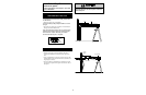
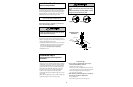

To reduce the risk of electric shock, your garage door
opener has a grounding type plug with a third grounding
pin. This plug will only fit into a grounding type outlet.
If the plug doesn't fit into the outlet you have, contact a
qualified electrician to install the proper outlet.
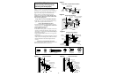
•If permanent wiring is required by your local code,
refer to the following procedure:
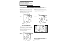
Right
Wrong
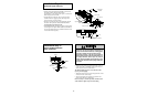
Ground Tab
Green
Ground Screw
Ground Wire
BlackWire
Permanent Wiring
Connection
White Wire
Black
Wire
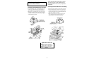
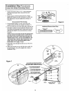
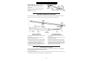
Installation Step 8
Electrical Requirements
To make a permanent connection through the 7/8" diam.
hole in the top of the opener (according to local code):
• Remove the opener cover screws and set the cover aside.
• Remove the attached 3-prong cord.
• Connect the black (line) wire to the screw on the brass
terminal; the white (neutral) wire to the screw on the
silver terminal; and the ground wire to the green
ground screw. The opener must be grounded.
• Reinstall the cover.
18
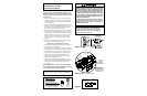
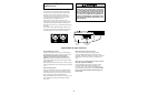
To prevent electrocution or fire,
installation and wiring
must be in compliance with local electrical and building
codes.
Do NOT use an extension cord, 2-wire adapter, or change
the plug in any way to make it fit your outlet.
To avoid installation difficulties,
do not run the opener until Step 9 below.
To prevent electrocution,
remove power from the
garage door opener
and
from the circuit you plan to
use for the permanent connection.
WARNING
WARNING
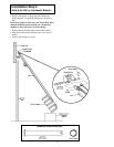
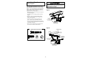
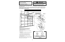
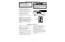
• Plug in the opener. If your door control has a Lock
feature, be sure it is off. Green indicator lights in both the
sending and receiving eyes will glow steadily if wiring
connections and alignment are correct. If the indicator
light is off in the receiving eye (and the invisible light
beam path is not obstructed), alignment is required.
• Loosen the receiving eye wing nut to allow slight
rotation of unit. Adjust sensor vertically and/or
horizontally until the green indicator light glows with a
steady light.
• When indicator lights are glowing steadily in both units,
tighten the wing nut in the receiving eye unit.
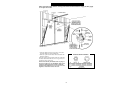
Trouble Shooting
1. If the sending eye indicator light does not glow
steadily after installation, check for:
• Electric power to the opener.
• A short in the white or white/black wires. These can
occur under staples or at screw terminal connections.
• Incorrect wiring between sensors and opener.
• An open wire (wire break).
2. If the sending eye indicator light glows steadily but
the receiving eye indicator light doesn't:
• Check alignment.
• Check for an open wire to the receiving eye.
Installation Step 9
Complete Safety Reversing Sensor
Installation