


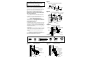
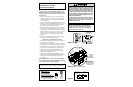
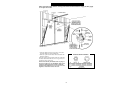
Multi-Function
Door Control Panel
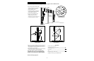
Terminal Screws
RED
WHITE
1
2
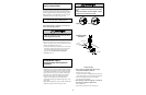
Lighted
Door
Control
Terminal
Screws
2-Conductor
Bell Wire
WHT
2
RED
1
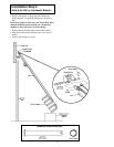
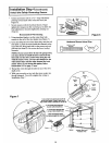
Installation Step 7
Install the Door Control
and Connect all Wiring
17
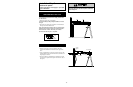
Children operating or playing with a garage door opener
can injure themselves or others.
The garage door could
close and cause serious injury or death.
Install the door
control (or any additional push buttons) out of the reach
of children and away from all moving parts of the door
and door hardware,
but where the garage door is visible.
Do not allow children to operate the push button(s) or the
remote control transmitter(s).
A moving garage door could injure someone under it.
Activate the opener only when the door is properly
adjusted, you can see it clearly, and there are no
obstructions to door travel.
Install Door Control
Locate the door control within sight of the door at a
minimum height of 5 feet where small children cannot
reach, and away from all moving parts of the door and
door hardware.
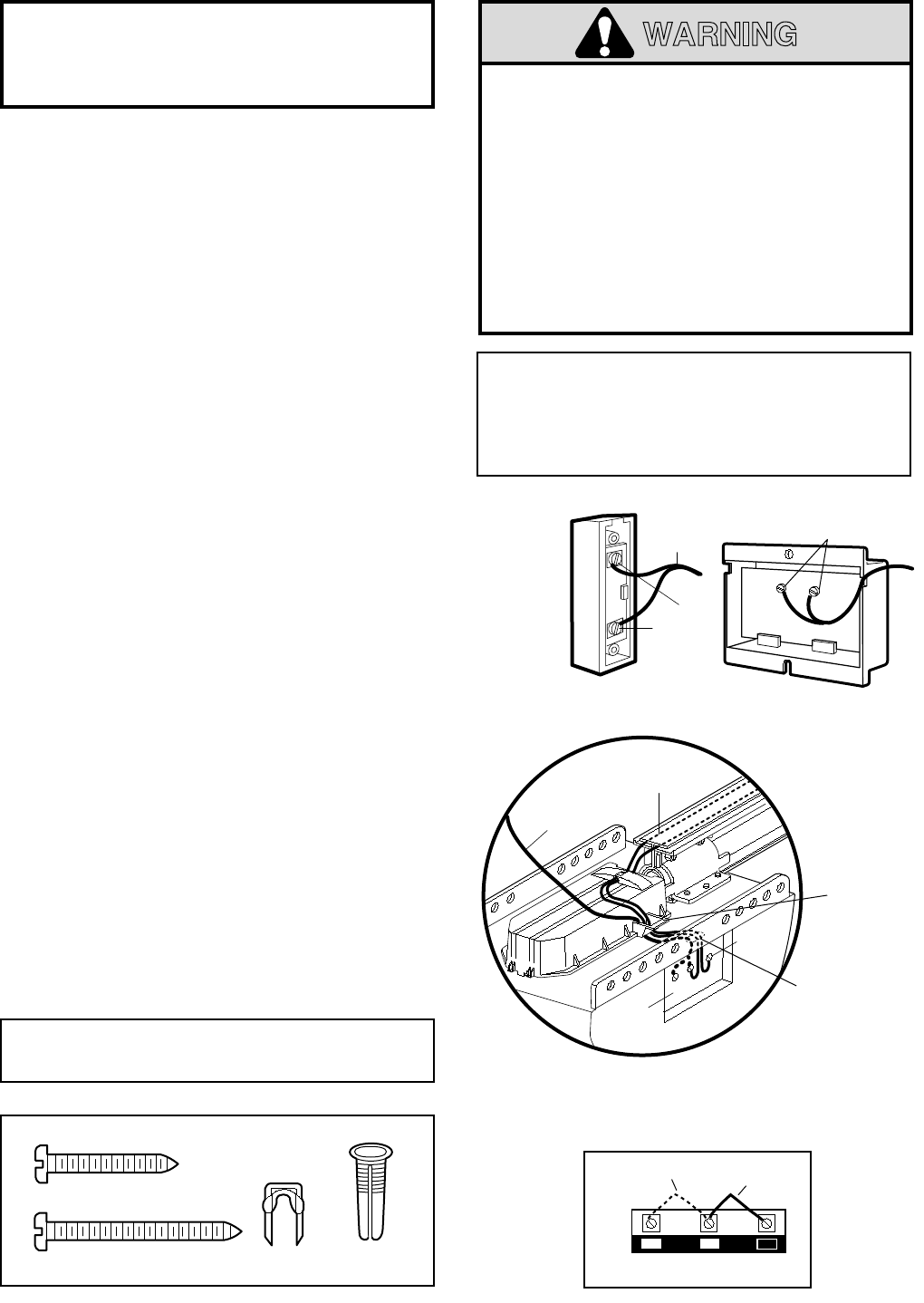
1. Strip 1/4" of insulation from one end of the bell wire
and connect it to the two screw terminals on the back
of the door control by color: white to 2 and white/red
to 1 (see Figure 1).
2. Fasten the Lighted Door Control Button securely with
6ABx1-1/2" screws. The Multi-Function Door Control
uses 6ABx1" screws. If installing into drywall, drill
5/32" holes and use the anchors provided.
3. Run the bell wire up the wall and across the ceiling to
the opener. Use insulated staples to secure the wire in
several places. Be careful not to pierce the wire with a
staple, creating a short. If your access door is near the
garage door, you may run this wire with the Safety
Reversing Sensor wires along the top of the rail. See
page 14.
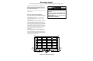
4. Remove the Control Center door on the right panel of
the opener to access the terminal screws.
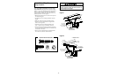
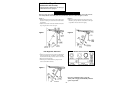
Connect Door Control and Sensor Wiring
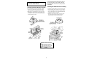
5. Thread all wires through the opening at the base of the
drive shaft cover (see Figure 2).
6. Insert the remaining wire through the hole in the power
unit and strip 1/4" of insulation from each set of wires.
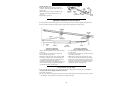
7. Connect the door control wire to the opener terminal
screws: white to 2 and white/red to 1. (See Figure 3.)
8. Separate the sensor white and white/black wires
sufficiently to connect to the opener terminal screws:
white to 2 and white/black to 3.
9. Attach the User Safety Instruction label to the wall
near the door control, and the Maintenance Instruction
label in a prominent location on the inside of the
garage door.
Page 28 explains how to operate the opener using the
door controls and the Lock & Light features available
on the Multi-Function Door Control Panel.
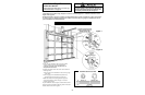
Dry Wall
Anchors
Insulated
Staples
6AB x 1" Screw
Multi-Function Door Control
6ABx1-1/2" Screw
Lighted Door Control Button
Hardware Shown Actual Size
Outside Keylock Connections (see Accessories)
To opener terminal screws: white to 2; white/red to 1
WARNING
Do NOT connect the power and operate the opener at
this time. The trolley will travel to the full open
position but will not return to the close position
until the sensor beam is connected and properly
aligned. See Step 9 on page 18.
OPENER TERMINAL SCREWS
(In Control Center)
Sensor
Connections
Door Control
Connections
(dotted line)
1
2
3
To
Door
Control
To
Sensors
Terminal
Screws
Control
Center
Figure 1
Figure 3
Figure 2 WIRING TO CONTROL CENTER
Insert wires
through
opening in
Drive Shaft Cover
Push wiring
through hole in chassis
(above Control Center)
and connect to opener
terminal screws