


7
Vermont Castings Vigilant
2000898
Clearances
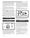
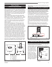
Your stove and chimney connector will radiate energy
in all directions when in operation. An important part
of planning a safe installation is to be sure combustible
materials near your stove do not overheat due to inad-
equate clearance.
Clearance is the distance between your stove (or chim-
ney connector) and nearby walls, ceiling, and floors, as
well as other combustible materials. Correct clearance
must also be maintained to moveable items, such as
furniture, newspapers, or clothes left to dry near the
stove. Keep all combustibles a considerable distance
away from the stove; 48” is a good minimum clear-
ance. Installing your Vigilant to the tested clearance
and keeping those clearance areas empty assures that
nearby surfaces will not overheat.
Clearances must be large enough so that furniture and
other combustibles near your stove will not overheat
and catch fire. Wood framing that is part of a wall
or floor will dry as it ages, and its ignition point (the
temperature at which it will start to burn) will be low-
ered. The change may take place slowly over a period
of many years, or more quickly if the wood is near a
source of heat such as a stove.
Your Vermont Castings Vigilant II Coal Stove has been
carefully and thoroughly tested by independent test-
ing laboratories to determine safe clearances. During
testing, heat sensors installed in all surfaces near the
stove and chimney connector, including floors and ceil-
ings, show the temperatures reached during a variety
of combustion situations. Clearance distances are
accepted only when the sensors show the stove is far
enough from nearby surfaces to meet strict UL or ULC
standards.
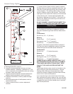
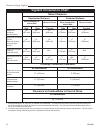
Using The Clearance Chart
If your stove will be parallel to the wall behind it (parallel
installation), use the columns of the chart labelled “side”
and “rear”. If your stove will be installed in a corner
(corner installation), use the columns labelled “corner”.
Your stove will be in either a parallel or a corner instal-
lation, not both. Use only the part of the chart that ap-
plies to your installation. Note: Side clearances do not
apply to corner installations.
Measure clearance between the edge of the stove’s top
plate and the nearby combustible surface. For most
common installations, when the stove has the proper
clearance from nearby surfaces, the chimney connector
will also have the proper clearance. However, instal-
lations vary. It is important to double check all installa-
tions for proper chimney connector clearance, as well
as stove clearance.
The clearance distance must be empty except for non-
combustible heat shields. Air flowing between the stove
(and/or chimney connector) and nearby shields car-
ries away heat. Do not block the air flow by filling this
empty space with any insulating material.
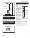
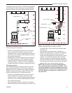
Clearance Reductions
When no shields are used, empty space alone provides
protection against overheating. When shields are used,
it is usually possible to reduce the required clearance,
as the shields offer additional protection.
Stove shields and connector shields (used only on
single-wall connectors) attach directly to the stove or
connector. Wall shields attach to wall surfaces. Combi-
nations of the these shield types may be used.
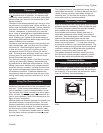
When shields are attached to the stove or chimney con-
nector, they are mounted 1” - 2” away from the stove
or connector surface on non-combustible spacers. The
shiny shield surface facing the heat source must be left
unpainted, enabling it to reflect heat back towards the
stove or connector and away from the wall.
The greatest clearance reductions result from using
both stove and chimney connector shields in conjunc-
tion with walls which are protected with wall shields.
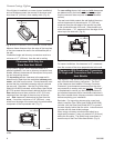
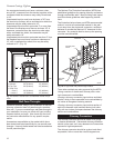
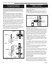
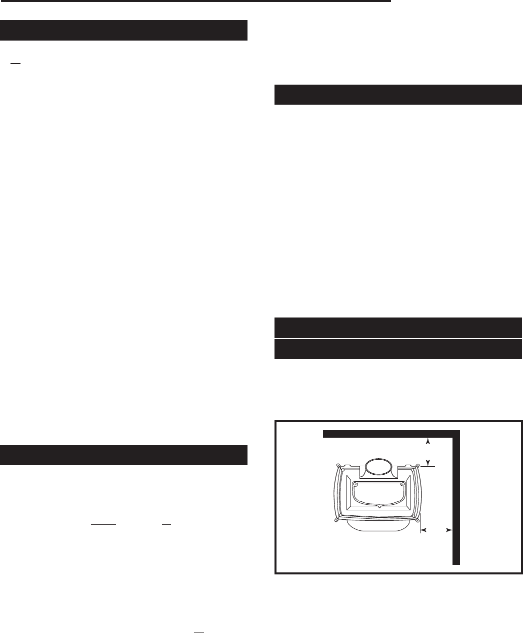
Unprotected Walls
Clearances With No Heat Shields
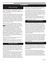
If the Vigilant is installed parallel to the rear wall (paral-
lel installation) and no shields are used, the stove must
be at least 20” (510 mm) from the wall behind it, and at
least 18” (460 mm) from walls beside it.
20" (510mm)
18"
(460mm)
ST683
Vigilant
clearances
parallel,
no heat shield
8/7/01 djt
ST683
Fig. 5 Minimum clearances, parallel installation, no heat
shield.