


10
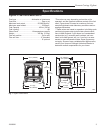
Vermont Castings Vigilant
2000898
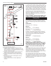
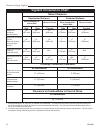
Vigilant II Clearance Chart
Unprotected Surfaces
Side Rear Corners Side Rear Corners
Stove in Corner
Stove Installed Par-
allel to Wall
Stove in Corner
Stove Installed Par-
allel to Wall
Stove Clearance
Protected Surfaces
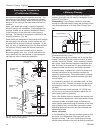
Chimney Connector Clearance
Single-wall
connector
No heat shields
Single-wall connector
Rear exit,
Rear heat shield
Double-wall connector
Top exit
Rear heat shield
Single-wall connector
Top exit
Rear and chimney
connector heat
shields
1
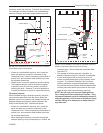
Single-wall connector
No connector heat
shields
Single-wall connector
Connector heat
shields installed
Double-wall
connector
All Installations
48” (1219 mm)
Clearance to Combustibles in Front of Stove
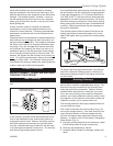
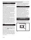
1. A ceiling heat shield, 24” (610 mm) in diameter and suspended 1” (25 mm) from the ceiling, must surround the chimney con-
nector in installations in which the chimney connector penetrates the ceiling. The chimney connector shield extends only to
24” (610 mm) above the flue colllar.
2. The ceiling heat shield required when the chimney connector shields are used should meet the wall protector. This will require
trimming the ceiling shield along the line of intersection with the wall protector.
All Installations
All Installations
18”
(457 mm)
20”
(508 mm)
16”
(406 mm)
7”
(178 mm)
13”
(330 mm)
9”
(229 mm)
18”
(457 mm)
13”
(330 mm)
16”
(406 mm)
7”
(178 mm)
11”
(279 mm)
9”
(229 mm)
18”
(457 mm)
13”
(330 mm)
N/A
7”
(178 mm)
11”
(279 mm)
N/A
15¹⁄₂”
(394 mm)
13”
(330 mm)
16”
(457 mm)
7”
(178 mm)
10¹⁄₂”
(267 mm)
9”
(229 mm)
17” (432 mm)
11” (279 mm)
12” (305 mm)
9” (229 mm)
9” (229 mm)
2
7” (178 mm)