


7
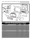
Vermont Castings VCBVTN/TP & VCPVTN/TP Room Heater
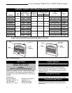
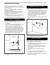
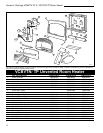
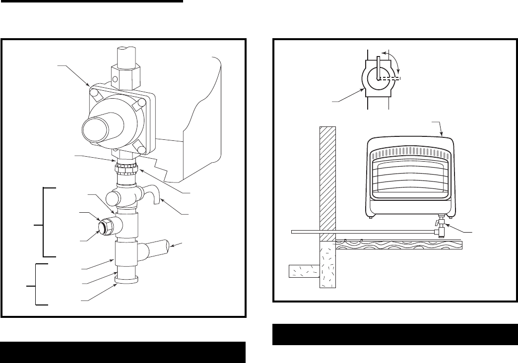
Pressure
Regulator
3/8” NPT Nipple
Tee Joint
Reducer
Bushing to
1/8” NPT
1/8” NPT
Plug Tab
Heater
Cabinet
Ground Joint
Union
Manual
Shutt-Off
Valve
From Gas
Meter
Test Gauge
Connection
Tee Joint
Pipe Nipple
Cap
Sediment
Trap
Natural Gas
(4” w.c. to
10.5” w.c. Pressure)
LP Gases
(11.5” w.c. to
14.0” w.c. Pressure)
RH103
Fig. 6 Gas line connection.
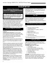
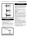
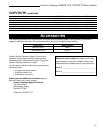
Open
Closed
Manual
Shut-Off
Valve
Manual
Shut-Off
Valve
Control Valve
RH104
Fig. 7 Manual shut-off valve location.
Leak Testing Heater Gas Connections
1. Open manual shut-off valve.
2. Open main gas valve located near gas meter.
3. Make sure control knob of heater is in the OFF
position.
4. Check all joints from manual gas valve up to control
valve and including the manifold assembly. Apply the
soap solution around the connections, valve and
tubing. Soap bubbles will appear where a leak is
present.
5. If a leak is present, immediately turn off gas supply,
tighten any leaky fittings, turn gas on and recheck.
6. To check burner and safety valve, the burner must
be lit (see Operating Instructions). Check the rest of
the connections for leaks.
7. Turn off the heater.
Pressure Test Gas Supply Piping System
The appliance and its individual shut-off valve must be
disconnected from the gas supply piping system during
any pressure testing of the system at test pressures in
excess of 1/2 psi.
The appliance must be isolated from the gas supply
piping system by closing the individual manual shut-off
valve (Fig. 7) during any pressure testing of the gas
supply system at test pressures equal to or less than
1/2 psi.