


6
Vermont Castings VCBVTN/TP & VCPVTN/TP Room Heater
Connect to Gas Supply
Before connecting the appliance, turn of all gas appli-
ances. Close the main gas valve at the gas meter or Lp
tank. Make certain there is good ventilation where the
installation will be made. Installation should comply with
all applicable building codes and ANSI Z223.1, latest
edition. Use LP gas resistant pipe compound to seal
threaded joints.
An installer supplied, design certified gas pressure
regulator must be installed to bring the gas supply
pressure down to 14” w.c.
WARNING: Never connect an unregulated gas line
to the heater.
IMPORTANT: Check gas line pressure before connect-
ing heater to gas line. Gas line pressure must not be
higher than 14” w.c. If gas line pressure is higher,
heater gas pressure regulator damage could occur.
NOTE: The gas line connection can be made with 3/8”
black or steel pipe. Internally tinned copper tubing may
be used in certain areas. Check your local codes. Use
pipe of large enough diameter to allow proper gas
volume to heater. If pipe is too small, undue pressure
loss will occur.
CAUTION: Use pipe joint sealant that is resistant to
liquefied petroleum gases.
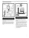
Install sediment trap in supply line as shown in Figure 6.
Locate sediment trap where it is within reach for
cleaning. Locate sediment trap where trapped matter is
not likely to freeze. A sediment trap prevents moisture
and contaminants from going into the heater controls. If
the sediment trap is not installed or is installed wrong,
the heater may not operate properly.
Test for gas leaks with a mild soap and water solution.
Apply water/soap solution with brush only -
do not over
apply. NEVER test with an open flame.
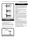
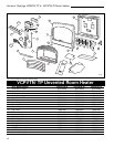
Floor Installation
1. The heater may only be installed on a noncombus-
tible flat surface. Wall mounting screws may be used
to keep heater from side movements.
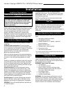
2. Measure heater mounting screws location “X” as
desired above floor. (Fig. 5)
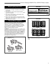
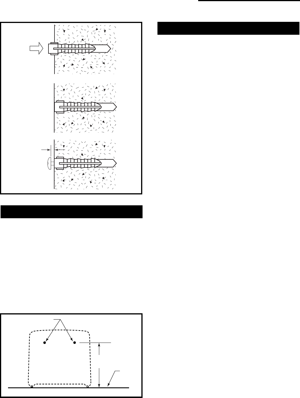
3. Use enclosed “paper template” for proper distance
between holes. Be sure template is level. It may be
necessary to use plastic or lead anchors for plaster
wall.
4. Drill holes at marked locations using 9/64” drill bit.
5. Leave screw head out from wall far enough to
attach heater.
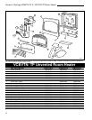
X
Screw Holes
Floor
RH107
Fig. 5 Optional wall mounting screw for floor installation.
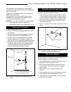
1/16"
(1.6mm)
RH102
Fig. 4 Wall anchor.