


10000836
7
Vermont Castings, Majestic Products RHE Natural Vent Insert
During any pressure testing of the gas line system,
when the test pressures are to exceed 1/2 psi (3.5 kpa)
the fireplace and its gas valve must not be connected
to that system.
At test pressures equal to or less than 1/2 psi, the gas
valve of the fireplace may be connected to the gas line,
but must be in the closed position.
Some municipalities have additional local codes, it is
always best to consult the local authority and the CSA-
B149.1 installation code in Canada.
FOR U.S.A Installations consult the current National
Fuel Gas Code, ANSI Z223.1
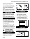
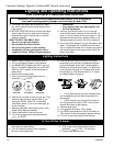
Always check for gas leaks with a mild soap
and water solution. Do not use an open
flame for leak testing.
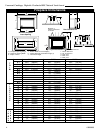
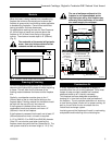
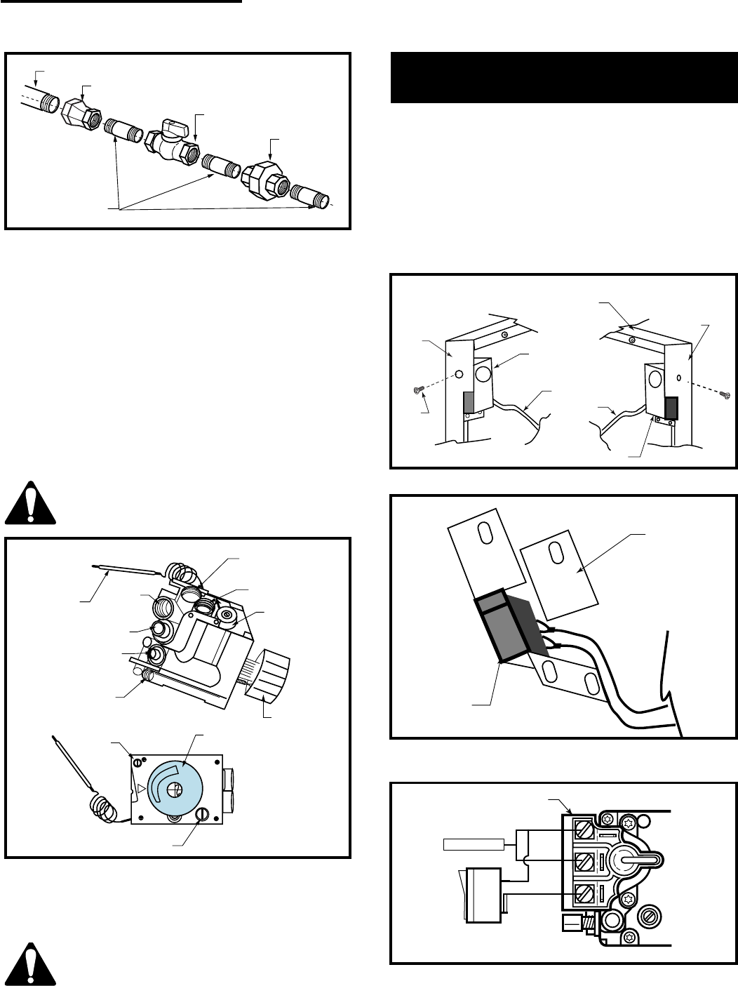
1/2" Gas Supply
1/2" x 3/8" Reducer
3/8" x 3/8" Shut Off
Valve
3/8" Union
3/8" Nipple
FP1278
Fig. 4 Typical gas supply installation.
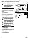
it
HI
LO
OFF
PILOT
Thermostat
Bulb
Brass
Plug
Gas Inlet
Thermocouple Inlet
Pilot Tube Entry
Manifold Gas
Outlet
Brass Plug
Pressure
Regulator
Control Knob
Control Knob
Pilot
Adjustment
Screw
Minimum Rate Screw
(Nonadjustable)
HV118
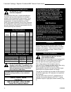
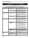
Fig. 5 On fireplaces equipped with the Eurosit 630 gas
valves, there are brass plugs in two of the holes. These
plugs are not to be removed. The gas inlet hole has a plastic
cap in it. Remove the plastic cap and connect your gas
supply line at this point.
The MN/MP valve control used on the
RHE25 does not include the thermostat
bullb as shown in Figure 5.
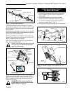
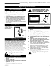
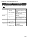
Installation of Remote Switch
for RN/RP Gas Valves
1. Thread wire through gas inlet opening on the right
side of fireplace. Do not cut wire or insulation on
metal edges.
2. Slide switch assembly from the back, between
subframe and trim, then fasten the screw. (Fig. 6)
3. For left side installation reverse switch position in
bracket and repeat Step 2. (Fig. 7)
4. Connect wiring to gas valve (Fig. 8a & b) and switch.
Right Side Installation
Left Side Installation
Trim Right
Side
Trim Top
Trim Left
Side
ON/OFF Switch
Assembly
Trim
Screw
Wiring from
Millivolt Gas
Valve
Trim
Screw
ON/OFF Switch Assembly
FP1253
Fig. 6 Slide switch assembly between subframe and trim.
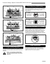
Bracket Switch
ON/OFF
Switch
FP1254
Fig. 7 For left side installation, reverse switch position in
bracket.
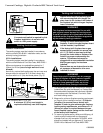
P
I
L
O
T
THTP
TP
TH
Valve
Thermopile
FP382a
Fig. 8a ON/OFF switch or millivolt thermostat.