


36
10000836
Vermont Castings, Majestic Products RHE Natural Vent Insert
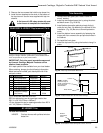
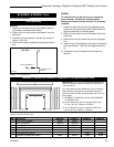
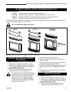
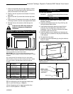
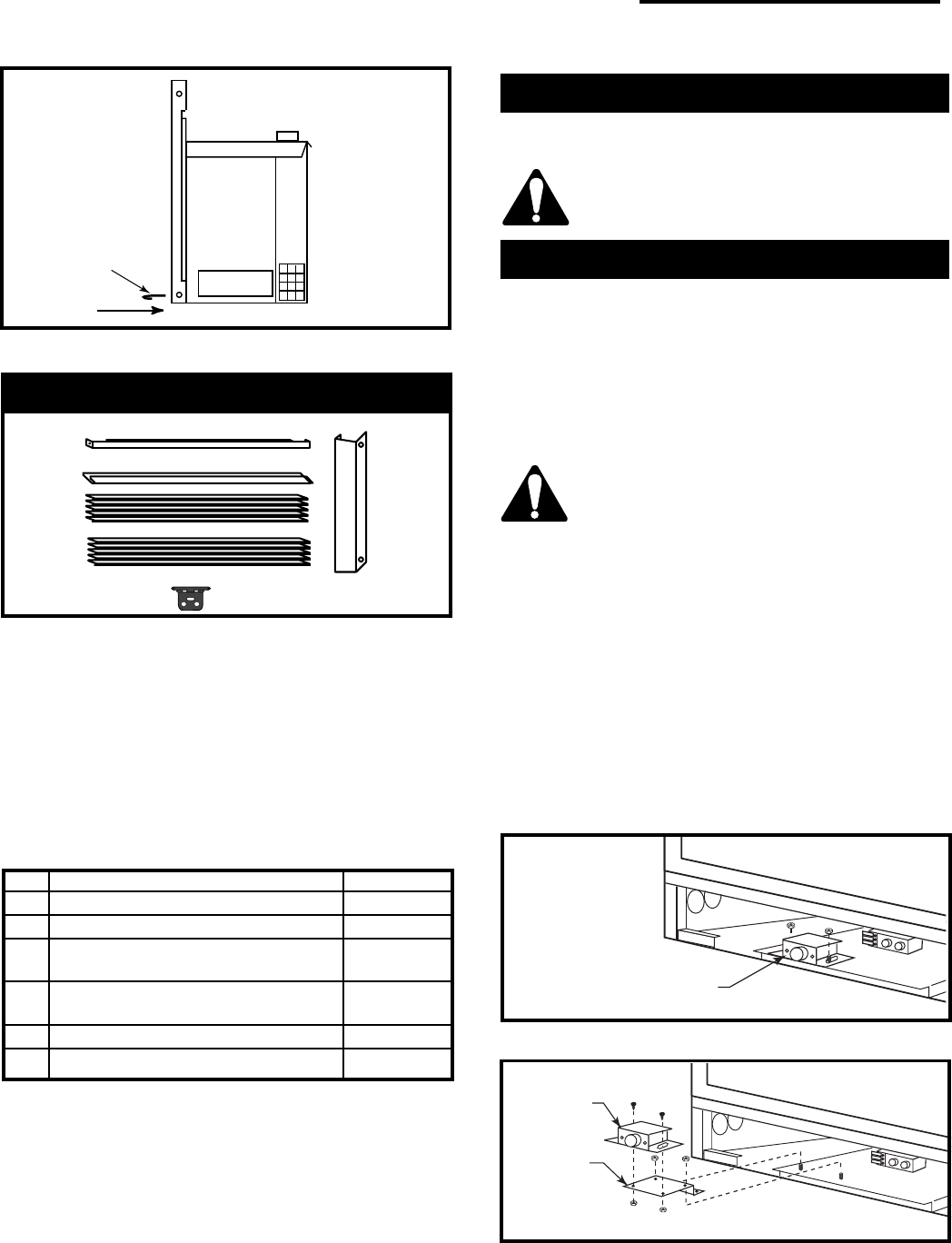
Bottom
Decorative
Plate
FP1292
Fig. 61 Slide bottom decorative plate under unit floor.
1
2
3
4
6
5
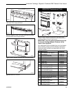
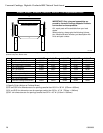
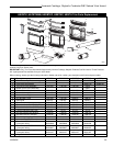
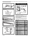
RHE42FP Replacement Parts
FP1296
Vermont Castings, Majestic Products reserves the right to make
changes in design, materials, specifications, prices and discontinue
colors and products at any time, without notice.
IMPORTANT: Only trim panel assemblies approved
by Vermont Castings, Majestic Products can be
used on these products.
ALL repair parts will be available from your local dealer.
When ordering, always give the following information:
Model and serial number, part description with finish
and part number.
Key Description RHE42FP
1 Trim Window Top/Bottom 10000880
2 Plate Decorative Bottom 10000915
3 Top Louvre Assembly (Metallic Black) 10000929
4 Bottom Louvre Assembly
(Metallic Black) 10000930
5 Hinge 52356
6 Hardware Package (Not Shown) 57916
C3 RHE42BTKP
For use with RHEDV42
RHE42BTKP Bay window with polished brass trim
Do not remove existing glass with frame.
Trim Assembly
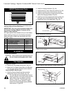
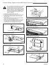
1. Reposition controls.
a. Remove the Fan Speed Control Box. (Fig. 62)
b. Attach the Fan Speed Control Box to the Bracket
(Fig. 61) and install the Bracket into the Cabinet.
Only for RN/RP VALVE units:
c. Install the Control Knob Extensions onto the
appropriate Control Valve Knobs. (Fig. 64)
On units fitted with a Honeywell brand control
valve the location of the control knobs and the
ignitor button may vary slightly from those
shown in Figure 64. The Honeywell extension
pieces are visually different in design and are
not interchangeable with the RN/RP knobs
shown in Figure 64.
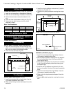
2. Install the hanging brackets. (Fig. 65)
3. Install the two (2) ceramic pieces inside the bay
window.
4. Install the bay window by hanging it onto the lower
tabs of the hanging brackets. (Fig. 66)
5. Install top louvre by engaging the oblong holes with
the upper tabs of the hanging brackets. (Fig. 67)
6. Install brass trim to the steel frame. (Fig. 68)
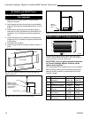
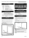
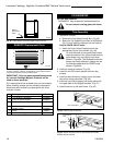
Fan Control Box
KT205
Fig. 62 Remove fan control box.
Fan Control
Box
Extension
Bracket
KT207
Fig. 63 Attach the control box to the bracket and install
bracket into the cabinet.