


6
10000836
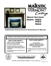
Vermont Castings, Majestic Products RHE Natural Vent Insert
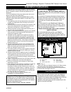
Zero Clearance Applications
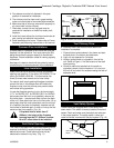
An alternate air supply is recommended
with this component.
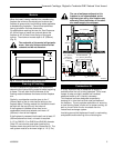
For installations other than in existing woodburning
fireplaces such as new construction or renovation
projects, a Zero Clearance Kit must be used. The kit
enables these inserts to be installed in combustible
environments. It is recommended that an Air Kit
(AKZC) be installed whenever using a Zero Clearance
Kit. Consideration must be given to the dimensions of
the Zero Clearance Kit and the requirements of the Air
Kit when planning the installation.
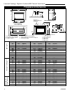
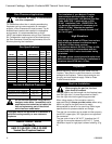
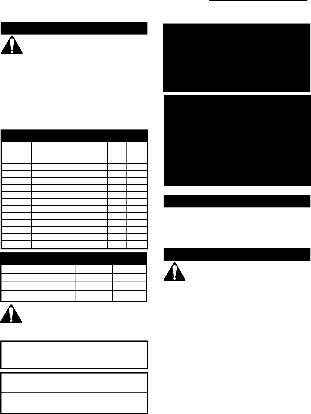
Gas Specifications
Max. Min.
Input Input
Model Fuel Gas Control Btu/h Btu/h
RHE25RN Natural Gas Millivolt HI/LO 22,000 15,400
RHE25RP Propane Gas Millivolt HI/LO 22,000 16,500
RHE25MN Natural Gas Manual HI/LO 22,000 15,400
RHE25MP Propane Gas Manual HI/LO 22,000 16,500
RHE3RN Natural Gas Millivolt HI/LO 30,000 21,000
RHE32RP Propane Gas Millivolt HI/LO 30,000 22,500
RHE32TN Natural Gas Thermostat HI/LO 30,000 21,000
RHE32TP Propane Gas Thermostat HI/LO 30,000 22,500
RHE42RN Natural Gas Millivolt HI/LO 40,000 28,000
RHE42RP Propane Gas Millivolt HI/LO 37,000 27,750
RHE42TN Natural Gas Thermostat HI/LO 40,000 28,000
RHE42TP Propane Gas Thermostat HI/LO 37,000 27,750
Natural LP
Minimum Inlet Pressure 5.5" W.C.11.0" W.C.
Maximum Inlet Pressure 14.0" W.C. 14.0" W.C.
Manifold Pressure 3.5" W.C. 10.0" W.C.
Gas Inlet & Manifold Pressures
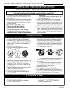
Do not use this appliance if any part of it
has been under water. Immediately call a
qualified service technician to inspect the
unit and replace any part of the control
which has been under water.
These gas inserts are approved for installation in
solid fuel burning masonry or zero clearance
fireplaces.
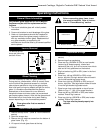
RHE25 / RHE32 / RHE42
Certified To
ANSI Z 21.88-2002 / CSA 2.33-2002
Vented Gas Fireplace Heaters
Preparation
Before beginning, remove the glass frame from the
fireplace. Also check to make sure there is no hidden
damage to the fireplace. Take a minute and plan out
the gas, vent and electrical supply. Refer to Glass
Frame Removal section.
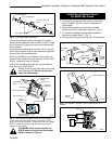
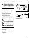
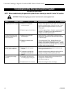
Gas Line Installation
When purging the gas line, the front
glass must be removed.
The gas pipeline can be brought into the fireplace base
from the right side. It is most convenient to install it
from the right side into the gas fittings provided.
When using copper or flex connector use only
approved fittings. Always provide a union when using
black iron pipe so that gas line can be easily
disconnected for burner or fan servicing. Refer to gas
specifications for pressure details and ratings.
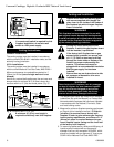
The gas line connection can be made of either properly
tinned 3/8" copper pipe, 3/8" rigid pipe or an approved
flex connector.
The gas control inlet is 3/8" N.P.T. therefore the 1/2"
rigid gas line must be reduced to 3/8" N.P.T. Typical
installation layout for rigid pipe is shown following. (Fig.
4)
The installation of your Majestic Fireplace
must conform with local codes, or in the
absence of local codes, with National Fuel Gas
Code, ANSI Z223.1 latest edition, or CSA-
B149.1 Installation Code. (EXCEPTION: Do
not derate this appliance for elevations up to
4,500 ft (1,370m). Maintain the manifold
pressure at 3.5" w.c. for Natural Gas and 10.0"
w.c. for LP gas.)
High Elevations
Input ratings are shown in BTU per hour and are
certified without deration for elevations up to
4,500 feet (1,370m) above sea level.
For elevations above 4,500 feet (1,370m) in USA,
installations must be in accordance with the
current ANSI Z223.1 and/or local codes having
jurisdiction.
In Canada, please consult provincial and/or local
authorities having jurisdiction for installations at
elevations above 4,500 feet (1,370m).