


7
NVC Series B-Vent
20000194
Gas Line Installation
When purging gas line the fornt glass
must be removed. Purging gas lines must
comply with ANSI Z223.1/NFPA 54 in USA
and CSA B149.1 in Canada.
The gas pipeline can be brought in through the right or
left side of the appliance, as well as the bottom. Knock-
outs are provided at convenient locations to allow for
the gas pipe installation and testing of any gas connec-
tion. It is most convenient to bring the gas line in from
the right side, as this allows fan installation or removal
without disconnecting the gas line.
The gas line connection can be made with properly
tinned 3/8" copper tubing, 1/2" rigid pipe or an approved
flex connector, then reduced to 3/8" (R Models) or 1/2"
(E Models) to the appliance. Because some municipali-
ties have some additional local codes, it is always best
to consult your local authority and the CSA-B149.1
installation code.
For US installations consult the current National Fuel
Gas Code, ANSI Z223.1/NFPA 54 .
Always check for gas leaks with a mild
soap and water solution applied with a
brush no larger than 1" (25mm). Never
aply soap and water solution with a spray
bottle. Do not use an open flame for leak
testing.
The fireplace valve must not be subjected
to any test pressures exceeding 1/2 psi.
Isolate or disconnect this or any other
gas appliance control from the gas line
when pressure testing.
The gas control is equipped with a captured screw type
pressure test point, therefore it is not necessary to
provide a 1/8" test point up stream of the control.
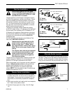
When using copper or flex connector use only approved
fittings. Always provide a union so that gas line can
be easily disconnected for burner or fan servicing.
Refer to gas specification for pressure details and
ratings. NOTE: If flex connector is used, it must be kept
inside of the appliance. (Fig. 5)
Remote Switch Installation
1. Thread wire through the electrical knockout located
on either side of unit. Do not cut wire or insulation on
metal edges. Ensure that wire is protected. Run the
other end to a conveniently located wall receptacle
box.
2. Attach wire to switch and install switch into receptacle
box. Attach cover plate to switch.
3. Connect wiring to gas valve. (Figs. 19 or 20, Page
14)
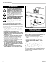
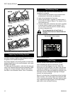
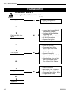
Alternate Switch Location
Remote switch can be installed on either side of the ac-
cess door. Simply mount the switch to the switch bracket
provided. Screw the bracket on either side of the frame,
lining up the screws with the pre-punched holes. (Fig. 7)
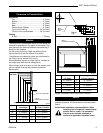
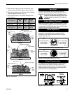
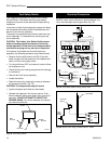
Fig. 5 Typical gas supply installation.
FP413
1/2" Gas Supply
1/2" x 3/8" Shut-off Valve
3/8" Union
3/8" Nipple
3/8"
Nipple
1/2" Gas Supply
1/2" x 1/2" Shut-off Valve
1/2" Union
1/2" Nipple
1/2"
Nipple
"R" Model
Supply Line
"E" Model
Supply Line
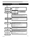
Fig. 6 Wiring diagram.
FP394
Black
White
Ground
Fan
Temperature
Sensor
Speed
Control
Fig. 7 Installing remote switch bracket.
FP381
Pre-punched
Holes