


6
NVC Series B-Vent
20000194
NVC36RN
NVC36RP
NVC36VN
NVC36VP
NVC36EN
NVC36EP
NVC39RN
NVC39RP
NVC39VN
NVC39VP
NVC39EN
NVC39EP
NVC43RN
NVC43RP
NVC43VN
NVC43VP
NVC43EN
NVC43EP
Natural
Propane
Natural
Propane
Natural
Propane
Natural
Propane
Natural
Propane
Natural
Propane
Natural
Propane
Natural
Propane
Natural
Propane
Millivolt Hi/Lo
Millivolt Hi/Lo
24V Hi/Lo*
24V Hi/Lo*
Electronic Ignition
Electronic Ignition
Millivolt Hi/Lo
Millivolt Hi/Lo
24V Hi/Lo*
24V Hi/Lo*
Electronic Ignition
Electronic Ignition
Millivolt Hi/Lo
Millivolt Hi/Lo
24V Hi/Lo*
24V Hi/Lo*
Electronic Ignition
Electronic Ignition
25,000
25,000
25,000
25,000
25,000
25,000
30,000
30,000
30,000
30,000
30,000
30,000
33,000
33,000
33,000
33,000
33,000
33,000
17,500
18,750
17,500
18,750
17,500
18,750
21,000
22,500
21,000
22,500
21,000
22,500
23,100
24,750
23,100
24,750
23,100
24,750
Max.
Input
Gas ControlFuelModel
Min.
Input
*To be used with PVS-1
Gas Specifications
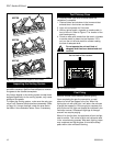
1. Choose the unit location.
2. Place the unit into position and secure it to the floor
with 1¹⁄₂” (38mm) screws, or nails. The holes to
secure the unit to floor are located just behind the
access door grille on the left and right side of the
unit.
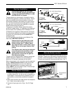
3. Frame in the fireplace with a header across the top.
It is important to allow for the finished wall face
when setting the depth of the frame.
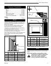
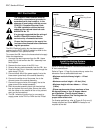
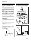
4. Attach the fireplace to the frame using the adjust-
able frame drywall strips (located behind the ac-
cess door for shipping). Preset the depth to suit
the facing material of the wall. The strips are adjust-
able to 1/2” (13 mm), 5/8” (16 mm), or 3/4” (19 mm).
(Fig. 4)
5. Screw through the slotted holes in the drywall strip
and into pre-drilled holes in fireplace side. Measure
from face of fireplace to the face of the drywall strip to
confirm the final depth.
Check fireplace to make sure it is levelled
and properly positioned.
Framing and Finishing
Final Finishing
Noncombustible materials such as brick or tile may be
extended over the edges of the face of the appliance.
DO NOT cover the window frame assembly, any
vent, louvre top assembly or louvre bottom assem-
bly.
If a Trim Kit is going to be installed on the fireplace, the
brick or tile will have to be installed flush with the edges
of the appliance.
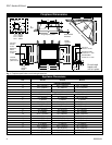
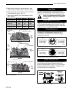
NVC36 / NVC39 / NVC43
CERTIFIED To
ANSI Z21.50a-2003 / CSA 2.22a-2003
Vented Gas Fireplace Heaters
High Elevations
Input ratings are shown in BTU per hour and are
certified without deration for elevations up to
4,500 feet (1,370m) above sea level.
For elevations above 4,500 feet (1,370m) in USA,
installations must be in accordance with the
current ANSI Z223.1/NFPA 54 and/or local codes
having jurisdiction.
In Canada, please consult provincial and/or local
authorities having jurisdiction for installations at
elevations above 4,500 feet (1,370m).
Natural LP
Minimum Inlet Pressure 5.5" w.c. 11.0" w.c.
Maximum Inlet Pressure 14.0" w.c. 14." w.c.
Manifold Pressure 3.5" w.c. 10.0" w.c.
Gas Inlet & Manifold Pressures
A
B
C
Fig. 4 Adjustable drywall strip (nailing flanges).
Adjustable Drywall Strip
(Nailing Flange)
Screw Drywall
Position Depths
A 1/2” / 13mm
B 5/8” / 16mm
C 3/4” / 19mm
FP1023
Adjustable
1/2”, 5/8” &
3/4” Spacing