


14
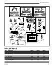
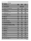
NVC Series B-Vent
20000194
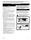
Vent Safety Switch
This fireplace incorporates the use of a Vent Safety
Shut-off Switch. The sensor and wiring are factory
installed and should not be removed or altered during
installation.
In the event of total flue blockage the system will detect
the increased heat buildup and will automatically shut
down the main burner assembly.
The sensor is located above the firebox behind the top
louvre assembly. It is accessible by removing the top
louvre assembly.
CAUTION: The firebox, Vent Safety Switch sensor
and surrounding panels become very hot during
normal operation. Allow time for the components to
cool before carrying out any service or inspection.
If the sensor is activated and shuts off the burner
assembly, the following procedure should be followed:
• Observe that the pilot flame is still ON. If the pilot
flame has gone out the reason for the fireplace shut
down is not the vent safety switch.
• Turn the pilot flame OFF and close all controls. Allow
the fireplace to cool.
• Check the flue and venting components for blockage
or restrictions.
• Remove the front louvre assembly.
• Locate the sensor.
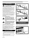
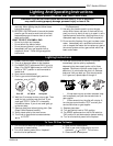
• Reset the sensor by pressing the reset pin between
the two wire terminals. (Fig. 18)
CAUTION: The components may still be hot.
• Light the fireplace and check for downdrafts.
• Operate the fireplace in the normal manner. If the
burner assembly shuts down again after a period of
operation, DO NOT ATTEMPT TO RESET THE
SENSOR AGAIN. Turn off the fireplace and contact
your service technician.
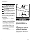
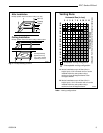
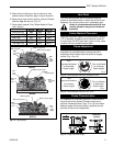
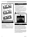
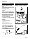
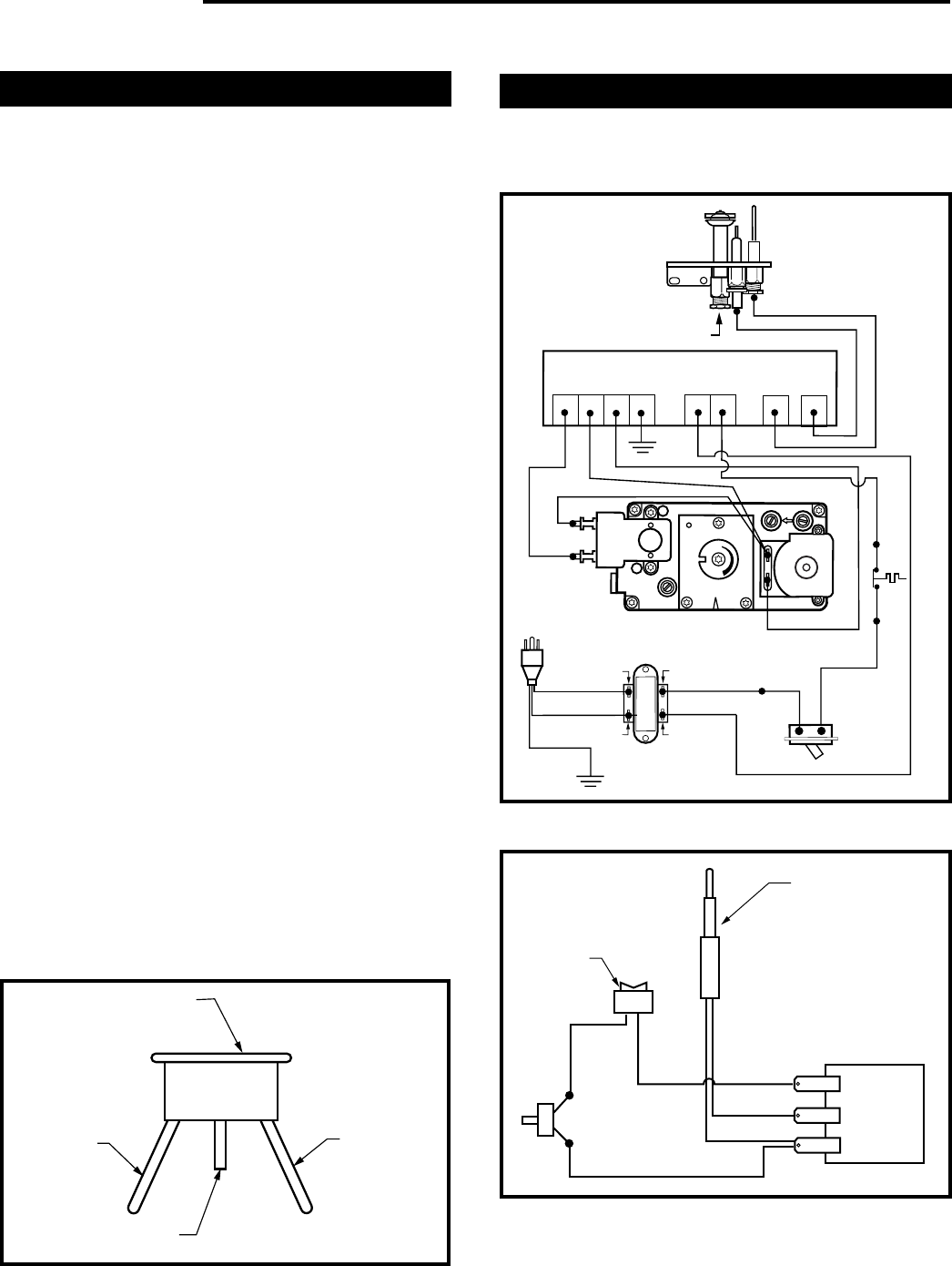
Electrical Connection
The sensor is wired in series between the wall mounted
ON/OFF switch and the Electronic Ignition Module (Fig.
19) or the thermopile and the gas valve (Fig. 20)
Sensor
Wire
Terminal
Reset Pin
FP1160
Fig. 18 Vent Safety Switch.
Wire
Terminal
24 VAC HOT
24 VAC RTN
ON-OFF
SWITCH
NOVA SIT 822 VALVE
HONEYWELL S8600 B IGNITION MODULE
120 VAC RTN
40VA
TRANSFORMER
120 VAC HOT
BLACK
BLACK
BLACK
BLACK
BLACK
BLACK
BLACK
WHITE
WHITE
WHITE
WHITE
WHITE
W
H
ITE
WHITE
WHITE
BLACK
PILOT
H
I
L
O
E
A
P
I
L
O
T
1 5
3 4
GREEN
MV MVPV PV
GND
(BURNER)
24V
GND
24V SENSE
SPARK
FP670
Fig. 19 Vent Safety Switch wiring, EN/EP units.
TH
TP
TH
TP
Gas
Valve
Thermopile
OnN/OFF
Switch
Vent
Safety
Switch
FP1161
Fig. 20 RN/RP units using a remote ON/OFF switch.