


20012914 7/05 Rev. 0
10
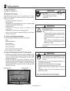
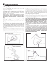
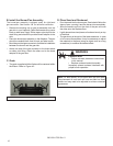
Figure 4.2 Center Grate Over Burner Pan
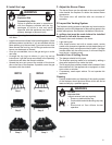
B. Install the Burner/Pan Assembly
The burner/pan assembly is shipped ready for right-hand
gas connection. See Section 3.B. for left-hand connection.
• Remove the existing cap or gas jet assembly from the
gas stub in your replace. Clean the threads using a wire
brush or steel wool. Apply Teon tape or pipe dope to the
steel tting and attach the provided brass adapter to the
stub.
• Place the burner/pan assembly in the replace. The pan
should be centered both front to back and side to side.
• Bend the provided gas connector to facilitate its installation
between the burner and the gas stub.
• Attach one end of the gas connector to the brass elbow
or safety pilot tting. Attach the other end to the brass
adapter at the gas tube.
C. Grate
• The grate, supplied with the rebox will be centered within
the rebox. Refer to Figure 4.2.
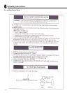
D. Place Sand and Rockwool
• Pour the sand into the burner pan. Sand should follow the
slope of pan, covering it and the burner tube completely.
• Allow the sand to spill out the front of the pan and over
the sides onto the replace oor.
• Lightly place dime-sized pieces of rockwool evenly on top
of the sand.
• The gas burns at the point of the least resistance. In case
of an uneven ame pattern it may be necessary to adjust
the materials in the pans (using an object such as a long
screwdriver) to achieve the desired effect.
Explosion Risk
• Follow rockwool placement instructions
in this manual.
• Replace rockwool material annually.
Improperly placed rockwool interferes with
proper burner operation.
WARNING
Note: For best results, do not pack down the rock wool.
The placement of rock wool can have an effect on ame
pattern and may need to be adjusted to achieve a desired
appearance.