


16
Vermont Castings EWF30
20008662
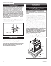
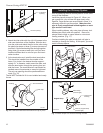
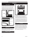
Side Wall Protection
Adjacent combustible side walls that are within mini-
mum dimensions shown in Figure 25 of the fireplace
opening must be protected with CFM Corporation Wall
Shield Model SP40 or a specifically built wall shield
described in Figure 20.
The special wall shield design described in Figure 20 is
an alternate method of adding protection to side walls
and can be used in place of the SP40 with the same
wall clearances specified for the SP40. Rt must =1.85
minimum.
Examples of wall shield insulation:
1. Manville - CERAFORM 126, K=.27,
1/2 inches thick
2. EH2416, K = .458,
1 inch thick required.
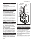
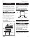
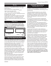
Hearth Installation
A hearth extension is required to protect a combustible
floor in front of the fireplace. Refer to Figure 26 for mini-
mum dimensions and mounting detail.
NOTE: Hearth Extension must not cover the air
inlet opening of a fireplace.
The hearth extension described in Figure 26 must be a
durable noncombustible material with a minimum (total)
Rt value of 1.09; see Figure 24 for examples. The over-
all height (above a combustible floor), depth and width
must be as indicated, with the extension centered to the
fireplace opening.
The top of insulation must be covered with a non-com-
bustible decorative covering or a piece of .018” mini-
mum sheet metal, to protect hearth extension material.
(Fig. 26)
Secure the hearth extension to the floor to prevent
shifting, using trim molding or other similar means at
three (3) outer edges. Seal crack between the fireplace
hearth and hearth extension with a noncombustible
material. (Figs. 25 and 26)
WARNING: Hearth extension must be installed in
accordance with Figure 25. Top of hearth extension
must be level with bottom of fireplace.
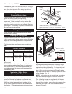
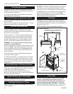
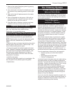
Alternate noncombustible materials may be used
providing the (total) thermal resistance (Rt value) of the
alternate material employed is greater than or equal to
R = 1.09 Thermal resistance (R) or thermal conductivity
(K), may be obtained from manufacturer of the material.
Factors are related by the formula K = 1/R. (Fig. 24)
T = given thickness
R = thermal resistance for a given thickness (T)
K = thermal conductivity
COMMON MATERIALS AND FACTORS
MATERIAL K*
R
MINIMUM
THICKNESS
EH2416
Common Brick
0.916
5.0
2.18 1.0 in.**
0.10 5.46 in.**
(CFM Corporation)
R Value is for 1/2 inch.
* Units of K = BTU/SQ FT/HR/˚F/IN
** Thickness of Listed Material
FP533ADD
Addendum
6/1/99 djt
8/4/99 changed .2 to .1
one inch to 1/2 inch djt
FP533ADD
Fig. 24 Hearth extension material factors.
NEW K of new material (per inch) thickness
required = X of listed
thickness K of listed material (per inch) material
FP1202a
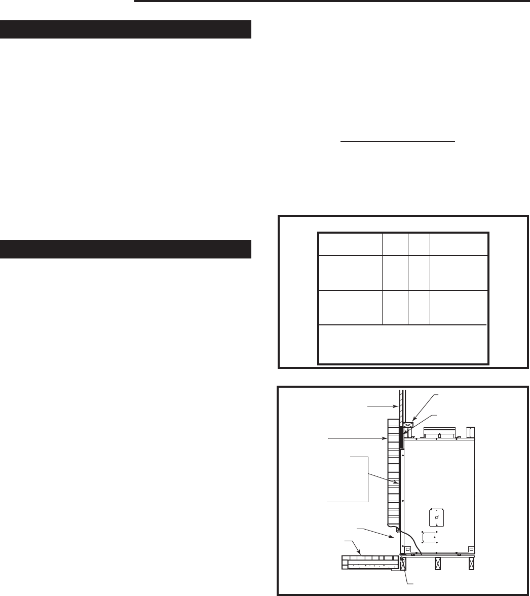
EWF30
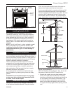
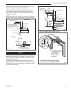
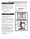
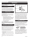
SEALING DETAILS
6/05
Wall Covering
2 x 4 Header - Do not
notch at standoffs
Noncombustible
Decorative
Facing
Seal all cracks
between fireplace sur-
round (steel) and wall
materials with noncom-
bustible material.
Cast Front
Noncombustible
Decorative
Covering
Safety Strips - Must be
overlapped 1/2” minimum
FP1202a
Fig. 25 Sealing gaps.
NOTE: No
material
may cover
black cast
face.
Noncombustible
Material
Noncombustible material with a lower R value may
be used, provided thickness of material is sufficiently
greater to maintain an equivalent (total) thermal resis-
tance (Rt).
Example of Determining Hearth Extension Equiva-
lents
To determine the thickness required for any
new mate-
rial:
Example for Common Brick
T (new) = 5.0/0.458 x 0.50 in. =
5.46 in. (new required
thickness).