


10002789/0 -5- DBT33/DBT36/DBT39
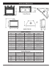
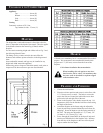
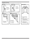
CLEARANCE TO COMBUSTIBLES
Appliance
Top.............................0 mm (0")
Bottom.......................0 mm (0")
Side............................ 0 mm (0")
Back........................... 0 mm (0")
Venting
Concentric sections of DV Vent
Top, bottom & sides ..25 mm (1")
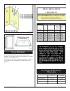
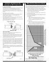
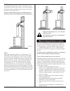
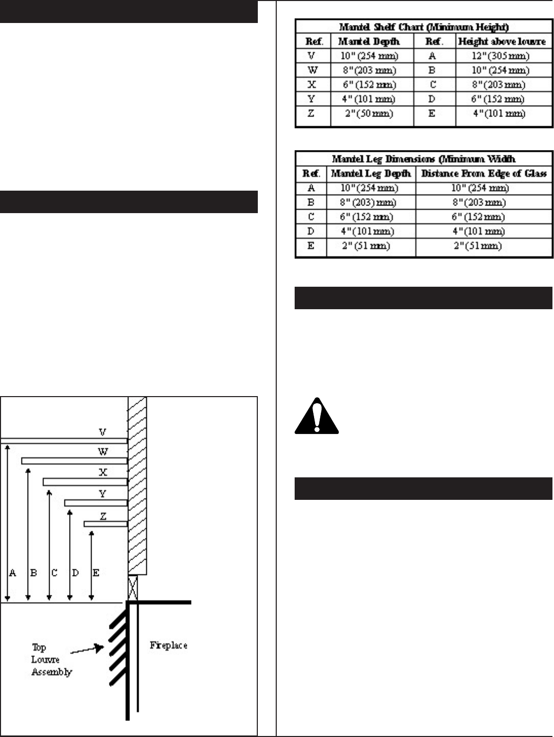
MANTELS
The height that a combustible mantel is tted above the re-
place is dependent on the depth of the mantel. This also applies
to the distance between the mantel leg (if tted) and the
replace.
For the correct mounting height and widths refer to Fig. 2 and
the following Mantel Charts.
The tting of a bay window trim kit does not effect the
distances and reference points referred to in the diagram and
chart.
Non-combustible mantels and legs may be installed at any
height and width around the appliance.
When using paint or lacquer to nish the mantel, such paint or
lacquer must be heat resistant to prevent discolouration.
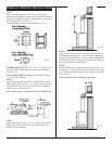
HEARTH
A Hearth is not mandatory but it is recommended for aesthetic
purpose. We recommend a non-combustible hearth which
projects out 12" (305 mm) or more from the front of the
replace.
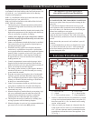
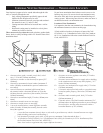
Cold climate Installation Recommendation:
When installing this unit against a non-insu-
lated exterior wall or chase, it is mandatory that
the outer walls be insulated to conform to appli-
cable insulation codes.
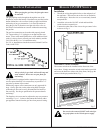
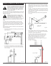
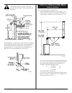
FRAMING AND FINISHING
1. Choose the unit location.
2. Place the unit into position and secure it to the oor with
1.5" (38 mm) screws, or nails. The holes to secure the
unit to the oor are located just behind the access door
grille on the left and right side of the unit.
3. Frame in the replace with a header across the top. It is
important to allow for the nished wall face when setting
the depth of the frame.
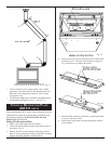
4. Attach the replace to the frame using the adjustable
frame drywall strips (located behind the access door for
shipping). Preset the depth to suit the facing material of
the wall. The strips are adjustable to 1/2"(13 mm), 5/8"
(16 mm) or 3/4" (19 mm), Fig. 3 & 4.
5. Screw through the slotted holes in the drywall strip and
into the pre-drilled holes in the replace side. Measure
from the face of the replace to the face of the drywall
strip to conrm the nal depth.
Fig. 2