


- 16 -
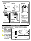
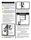
DO NOT BACK FILL AROUND SNORKEL.
SOIL SHOULD NOT BE LESS THAN 4"
(100mm) BELOW SNORKEL.
FOUNDATION
RECESS
SNORKEL
SCREWS
WALL
SCREWS
SHEET METAL
WATERTIGHT
SEAL
AROUND
PIPE
If the foundation is recessed, use recess brackets (not
supplied) for securing lower portion of the snorkel. Fasten
brackets to wall first and then secure to snorkel with self
drilling #8 x 1/2 sheet metal screws. It will be necessary to
extend vent pipes out as far protruding wall face (Fig. 32).
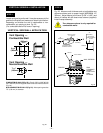
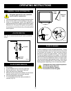
VERTICAL THROUGH THE
ROOF APPLICATIONS
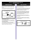
This Gas Fireplace has been approved for,
a) Vertical installations up to 40 feet (12 metres) in height.
Up to a 10 ft.(3048mm) horizontal vent run can be
installed within the vent system using a maximum of
three 90
o
elbows.
b) Up to two 45
o
elbows may be used within the horizontal
run. For each 45
o
elbow used on the horizontal level
the maximum horizontal length must be reduced by 18
inches (457mm).
Example: Maximum horizontal length
0-45
o
elbows 10 ft. (3048mm)
1-45
o
elbows 8.5 ft. (2590mm)
2-45
o
elbows 7 ft. (2133mm)
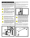
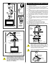
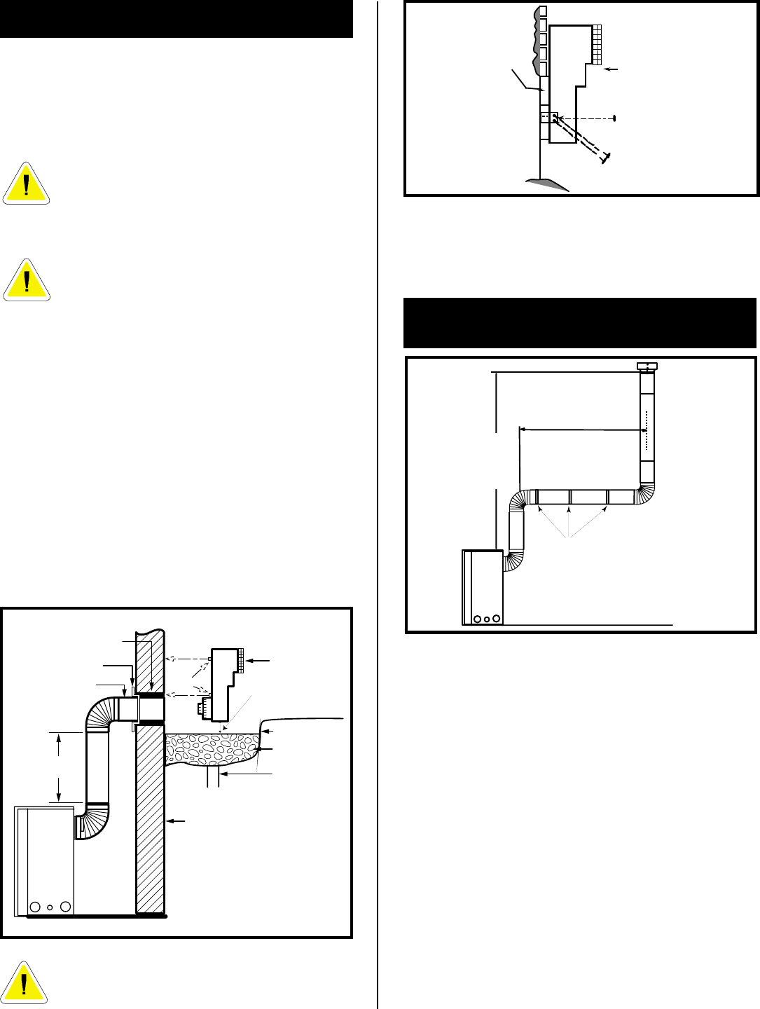
BELOW GRADE INSTALLATIONS
When it is not possible to meet the required vent terminal
clearances of 12 inches (305mm) above grade level a
model #7DVSKS vent kit is required. It allows installation
depth of down to 7 inches (178mm) below grade level. The
7 inches is measured from the centre of the horizontal vent
pipe as it penetrates through the wall.
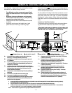
If venting system is installed below ground,
we recommend a window well with adequate
and proper drainage.
Ensure sidewall venting clearances are observed.
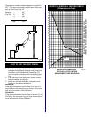
T
he maximum horizontal run with 24" (610mm)
vertical rise is 36" (914mm) from the back of the
fireplace to the face of the exterior wall. See
vent graph (Fig. 21) for extended horizontal run
if the vertical exceeds 24" (610mm).
1. Establish vent hole through the wall. See page 14
2. Remove soil to a depth of approximately 16"
(406mm) below base of snorkel. Install window well
(not supplied). Refill hole with 12" (305mm) of
coarse gravel leaving a clearance of approximately 4"
(100mm)below snorkel. (Fig. 31)
3. Install vent system. See page 13, Steps 2 through 5.
4. Ensure a watertight seal is made around the vent
pipe coming through the wall.
5. Apply high temperature sealant caulking (supplied)
around the 4 and 7 inch 7DVSKS's snorkel collars.
6. Slide into vent pipe and secure to the wall.
7. Level the soil so as to maintain a 4"
(100mm)clearance below snorkel (Fig. 31).
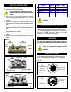
Fig. 33
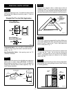
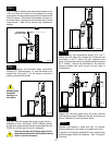
c) A minimum of an 8 ft. vertical rise.
d) Two sets of 45 degree elbow offsets within these
vertical installations. From 0 to a maximum of 8 ft.
(2438mm) a vent pipe can be used between elbows.
(Fig. 35)
e) 7DVCS must be used to support offsets. (Fig. 35)
This application will require that you first determine the roof
pitch and use the appropriate 7DVSKV (A,B or F). (see
Venting Components, page 28)
Fig. 31
Fig. 32
MAXIMUM
10 FT
(3048mm)
PIPE STRAPS
EVERY 3'
(914mm)
MINIMUM
8 FT./
MAXIMUM
40 FT.
VERTICAL
RISE
GRAVEL
DRAIN
FIRESTOP
FOUNDATION WALL
WINDOW WELL
7DVSKS
(SNORKEL)
GROUND
24"/608mm
MINIMUM*
7" PIPE
SCREWS
MINIMUM
4" CLEARANCE
ZERO CLEARANCE
SLEEVE IF REQUIRED
A minimum of 24"/608mm
vertical pipe must be installed when
using the 7DVSKS/7TDVSKS kit.
The 22" vertical rise (center to
center) of the snorkel may be
included for calculation of max.
horizontal run.
*
*