


5
INSTALLATION
1. Remove all parts from inside the stove body.
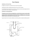
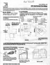
2. Select the proper location for the stove. These appliances must not be installed any closer than the
minimum clearance to combustible materials shown in Figure A (on diagram sheet). The stove must be
installed on a non combustible surface as shown in Figure A (on diagram sheet).
3. If non combustible materials have been installed on the walls, obtain the minimum clearances from
either the manufacturer of these materials or the local building inspectors office.
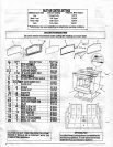
4. Install the refractory bricks (see Figure B on diagram sheet).
5. Install the stovepipe INSIDE the flue collar on the top of the stove between the stove and chimney.
6. DO NOT use a grate to elevate the fire.
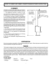
STOVE PIPE
1. A clearance of 18 inches (457mm) between the stovepipe and combustible materials may be required.
Check with authorities having jurisdiction in your area.
2. All pipe sections must be connected with the male end (crimped end) toward the stove.
3. Fasten the stove pipe to the flue collar by the use of three sheet metal screws. Do the same at each
additional joint to make the entire installation rigid.
4. Maintain the required diameter flue for the entire installation.
5. If you are connecting the stove to an old masonry flue, be sure to have it inspected for cracks and
general condition. Resizing with a stainless steel liner may be required.
6. It is recommended that no more than two 90 degree bends be used in the stovepipe installation. More
than two 90 degree bends may decrease the amount of draw and possibly cause smoke spillage.
7. A damper is not required in this installation. Remove damper plate in the chimney or secure in the
OPEN position.
8. Single wall flue pipe assemblies must not exceed 10 feet (3 metres) in overall length.
FAILURE TO FOLLOW THE MINIMUM CLEARANCE REQUIREMENTS MAY RESULT IN AN
UNSAFE INSTALLATION.