


8
8
Radiance Natural Vent Gas Heater
20004409
Tools Required
• Phillips screwdriver (stub) • power drill
• utility knife • reciprocating saw
• metal drill bit: size 28 (.140"/3.5mm)
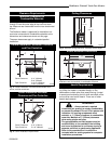
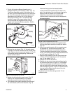
Unpack and Set Up the Stove
The Radiance is shipped on its back. Cut the shipping
straps and set stove upright.
Parts Bag Contents:
•
On-Off switch, housing, and wiring harness
• 2 Bags of Lava Rock • 7 Screws
• Pipe Support Bracket • Fan Bracket*
• Door Handle (Operable) • Control Door Handle
• Owner Registration Card
• (4) CS, Hex Hd 3/8-16 x 1 GR 2-Z
• (4) Washer, FL 3/8-Z
*Used with stove’s having serials #’s starting at #1457
(RNVODRN), #1944 (RNVODRP).
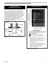
Unpack and Assemble Legs
The Radiance is shipped upright. Cut the shipping
straps and set stove upright.
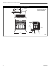
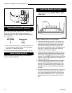
1. Slide stove to the rear of the pallet just far enough
to access rear leg holes. Make sure the stove does
not tip over backwards. (Fig. 8)
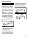
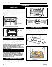
Install the Optional Fan
These instructions are for stoves with serial numbers
up to #1456 (RNVODRN), #1943 (RNVODRP).
If you are installing the optional convection Fan Kit
#2767 (FK26), continue here. It is easiest to install fan
kit before connecting gas line. If you are not installing a
Fan Kit, proceed to Venting System Assembly.
WARNING
This appliance is equipped with a three-prong
(grounded) plug for your protection against shock
hazard and should be plugged directly into a
properly grounded three-prong receptacle. Do not
cut or remove the grounding prong from this plug.
ST720
Fig. 8 Slide stove back just far enough to access rear leg
holes.
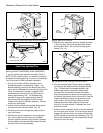
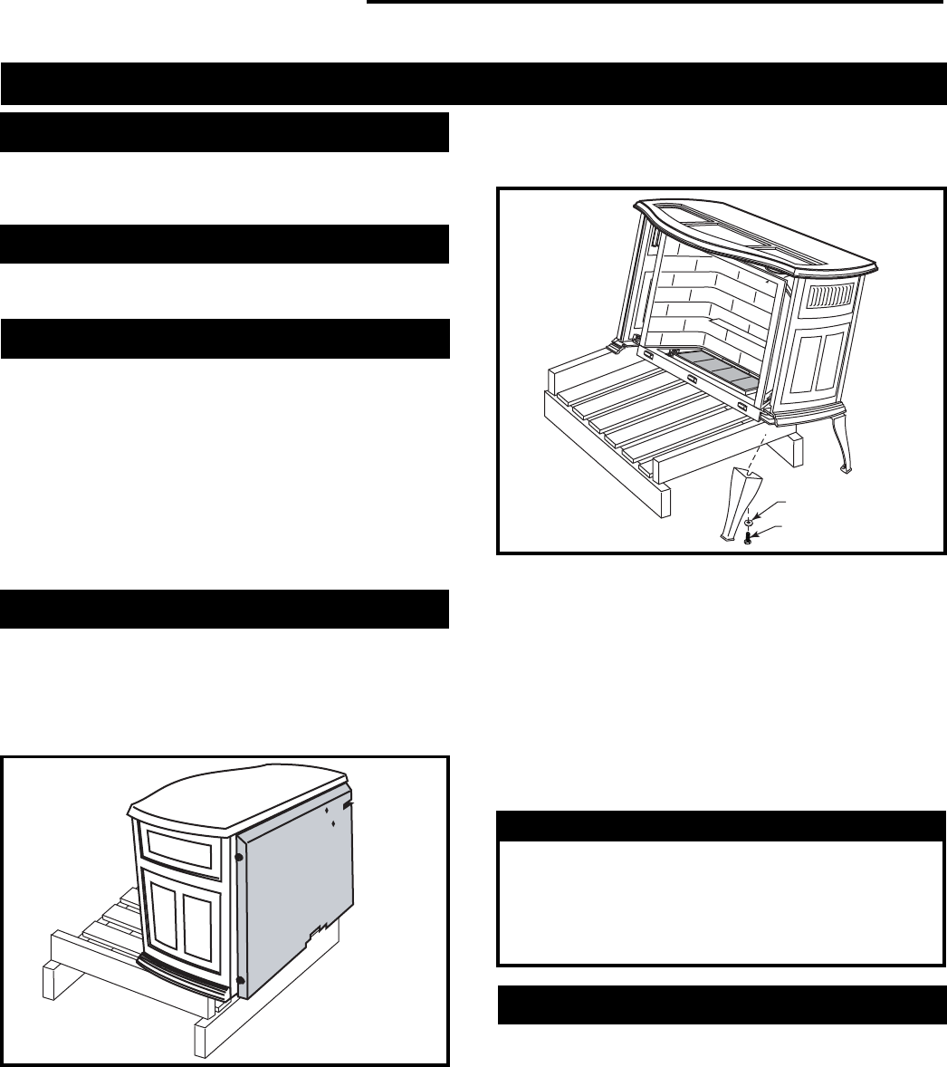
2. Attach the rear legs using 3/8” hex head bolts and
flat washer supplied. Tighten with a 9/16” wrench or
socket.
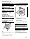
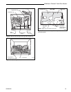
3. Carefully tip the stove onto its rear legs. Adjust the
pallet to allow access to one of the front leg holes.
Be sure to leave the pallet under the stove to
prevent the stove from falling fully forward. (Fig. 9)
CAUTION: To prevent valve tubing from being
crushed or damaged, make sure to rest valve on
wooden pallet.
Washer
Hex Head Bolt
ST721
Fig. 9 Carefully tip stove onto back legs. Leave pallet under
stove to keep stove from falling fully forward.
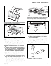
4. Have your assistant attach one leg using the
hardware described.
5. Move the pallet to allow access to the other front leg
hole. Attach remaining leg.
6. Remove pallet and allow stove to gently rest on all
four legs.
7. Adjust leg levelers to compensate for irregularities
in the hearth.
Assembly Procedures