


21
Vermont Castings Pinnacle & Stardance Direct Vent - Rear Vent Gas Heaters
20003457
#7DVAIS
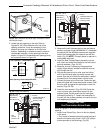
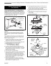
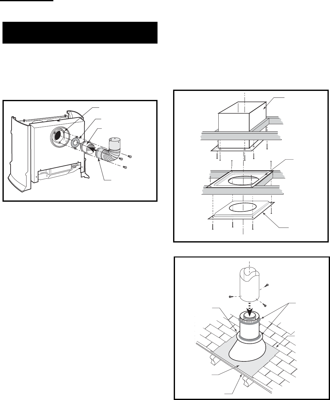
Attic Insulation
Shield
#7DVFS
Firestop in
Upper Floor
#7DVFS
Firestop in
Ceiling
Use Four
8d Nails
ST222
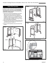
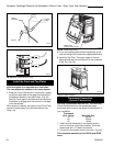
Fig. 40 Install firestops and attic insulation shield.
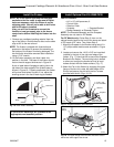
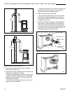
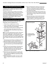
Storm
Collar
Sealant
Upper edge
of flange
goes under
upper
shingles
Flashing
#7DVSKV
(A, B, or F)
Roof Support
Use three #5
sheet metal
screws at
each joint
ST221
Fig. 41 Roof support and flashing.
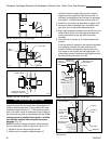
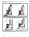
Vertical (Through the Roof)
Vent Assembly
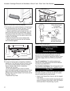
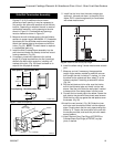
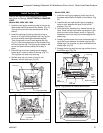
NOTE: All vertically terminated installations must,
where specified, use the 2¹⁄₄” restrictor plate, to
comply with Vertical Termination Window (Fig. 8,
Page 9), included in the hardware bag. The plate must
be installed within the firebox inner flue collar to insure
a proper air/fuel ration is maintained in an appliance
vented through the roof. (Fig. 39)
Inner Flue Collar
2¹⁄₄” Restrictor Plate
Vent Starter Pipe
Seal all
around
crimped end
ST398a
Fig. 39 Install restrictor plate and starter pipe/inner elbow
assembly.
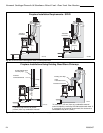
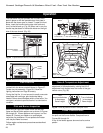
8. Install appropriate pipe sections until the vent run
reaches above the flashing. The enlarged ends of
the vent sections always face downward.
9. Install the storm collar and seal around the joints. (Fig.
41)
10. Add additional vent lengths to achieve the proper
overall height.
11. Install termination cap.
Make certain the vent system conforms to all other
requirements for vertical termination as specified on
Page 9.
This installation will require you to first determine the
roof pitch and use the appropriate vent components.
Refer to Figure 9, Page 10.
1. Locate the final position of the stove, observing all
clearances for both the vent and the stove.
2. Plumb to the center of the inner (4”) flue collar from
the ceiling above, and mark that location.
3. Cut the opening: (Fig. 31, Page 20)
9³⁄₈” x 9³⁄₈” (240mm x 240mm)
4. Plumb any additional opening through the roof or
other construction that may be needed. In all cases,
the opening must provide a minimum of 1” (25mm)
clearance to the vent pipe.
5. Place the stove in its final position.
6. Install firestop(s) #7DVFS and Attic Insulation Shield
#7DVAIS as needed. (Fig. 40) If there is a room
above ceiling level, a firestop must be installed on
both the bottom and top sides of the ceiling joists. If
an attic is above ceiling level, an attic insulation
shield must be installed.
7. Install the appropriate roof support and flashing,
making certain that the upper flange of the flashing
base is below the shingles. (Fig. 41)