


35
Vermont Castings Pinnacle & Stardance Direct Vent - Rear Vent Gas Heaters
20003457
Fuel Conversion Instructions
WARNING! This conversion kit shall be installed
by a qualified service agency in accordance with
the manufacturer’s instructions and all appli-
cable codes and requirements of the authority
having jurisdiction. If the information in these
instructions is not followed exactly, a fire,
explosion or production of carbon monoxide
may result causing property damage, personal
injury or loss of life. The qualified service
agency is responsible for the proper installation
of this kit. The installation is not proper and
complete until the operation of the converted
appliance is checked as specified in the
manufacturer’s instructions supplied with the
kit.
CAUTION: The gas supply shall be shut off prior
to disconnecting the electrical power, before
proceeding with the conversion.
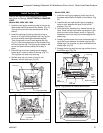
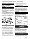
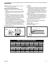
PILOT
O
N
O
F
F
PILOT
ADJ
L
O
H
I
Main
Gas Line
Gas Supply Inlet
ST226
Fig. 68 Attach the gas line to the right side of the valve.
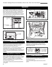
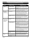
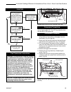
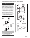
If the manual switch is
set to REMOTE,
press the mode button
to display AUTO on the
transmitter. Does the
transmitter display the
room and temperture
setting?
If the settings is above
room temperture on the
transmitter, does the
main valve and fan
turn on?
Turn pilotstat knob to
OFF to turn valve
completely off.
Auto Path
Move switch from
LOCAL to REMOTE.
Press any key within
30 seconds.
Yes
Yes
No
No
If the settings is below
room temperture on the
transmitter, does the
main valve and fan
turn off?
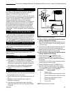
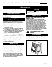
Conversion Precautions
Before proceeding, turn control knob on valve to OFF
and turn gas supply OFF. Turn OFF any electricity that
may be going to the appliance.
Conversion Procedure
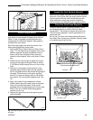
1. Remove stove front. Lift stove front up and then
swing bottom out and away to disengage from the
stove body. (Fig. 49, Page 26)
2. Swing open the swiveling latches at the top left and
right corners of the glass frame. (Fig. 78, Page 38)
3. Pull the top edge of the glass and frame assembly
away from the firebox face. Place the assembly out of
the way on a flat, padded surface such as a counter
protected by a towel.
4. Remove the logset from the firebox.
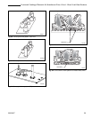
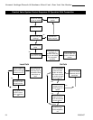
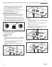
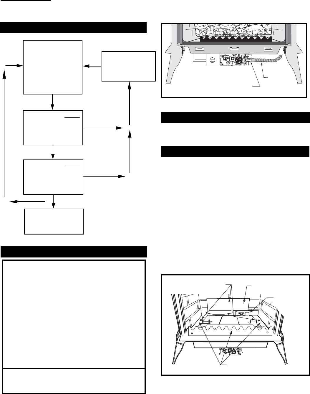
5. Remove the rear log bracket by unfastening the
screw. (Fig. 69)
6. Remove the right and left log bracket assembly by
unfastening the two screws which hold the burner in
place. (Fig. 69)
Remove Screws
Rear Log Bracket
Pilot
Left & Right Log
Bracket Assembly
ST350
Fig. 69 Remove rear log bracket and left and right log bracket
assembly.