


17
Vermont Castings Pinnacle & Stardance Direct Vent - Rear Vent Gas Heaters
20003457
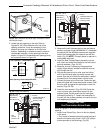
3. Measure the wall thickness and cut the wall sleeve
sections to proper length (MAXIMUM 12”). Assemble
the sleeve with the #8 sheet metal screws supplied.
Attach the firestop plate to the sleeve end with the
holes. (Fig. 32) NOTE: The wall sleeve is required in
combustible walls only.
4. Install the Wall Firestop/Sleeve assembly into the
wall cutout and fasten the firestop to the wall cutout
framing members. (Figs. 25, 26)
5. Measure, and cut if necessary, the appropriate
length of pipe section needed to make the connec-
tion through the wall.
6. Slip the wall plate and trim collar over the interior
end of the horizontal pipe and install into the wall
sleeve. Seal the joint inside the wall plate if needed
to keep cold air from being drawn into the home.
7. Connect the pipe to the inner collar. Fasten the wall
plate to the pipe with three sheet metal screws. Slide
the trim collar up against the wall plate to cover the
screws. (Figs. 25, 26)
8. Install the vent terminal. (Figs. 25 & 26) Guide the
inner and outer vent termination collars into the
adjacent pipes. Double check that the vent pipes
overlap the collars by 2”. Fasten the termination to
the wall with the screws provided, and caulk the joint
with weatherproof sealant.
Through Side Wall /
Vent Termination Below Grade
Refer to Figures 27 & 28 for minimum centerline of wall
opening.
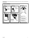
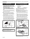
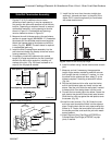
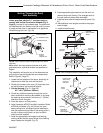
1. Attach Inner Starter Pipe, (found in with the logset),
to the stove.
• Run a bead of sealant beneath the pipe bead and
attach to the stove using three 1/4-20 x 3/8” phillips
screws provided in the parts bag. (Fig. 29)
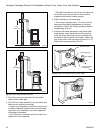
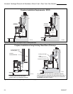
25³⁄₄"
(654mm)
to Top of
Opening
Firestop
Ventilated Wall Plate -
Open End Down
Finishing Collar
Seal
Around
Terminal
9³⁄₈” W x 10³⁄₈” H
Wall Opening
ST400
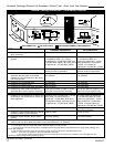
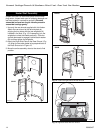
Fig. 26 PDV20 with Rear Vent Kit 7TFSRSK installation.
Wall Sleeve -
Seal Around
2. Locate the vent opening on the wall. Refer to
Figures 24, 25 & 26 to determine the top of the
opening centerline. It may be necessary to first
position the stove and measure to find the hole
location. Depending on whether the wall is made of
combustible materials, cut the opening to the size
shown in Figure 24. Combustible wall openings must
be framed as shown in Figure 24
Sealant
Phillips
Screws
ST396
Fig. 23 Apply sealant to the starter pipe, and fasten to stove
with Phillips screws.
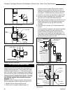
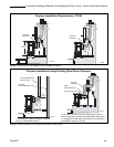
27³⁄₈"
(695mm)
to Top of
Opening
Firestop
Ventilated Wall Plate -
Open End Down
Finishing Collar
Seal
Around
Terminal
9³⁄₈” W x 10³⁄₈” H
Wall Opening
ST400
Wall Sleeve -
Seal Around
Fig. 25 SDVR with Rear Vent Kit 7TFSRSK installation.
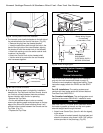
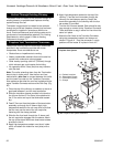
9³⁄₈"
(240mm)
10³⁄₈"
(265mm)
7¹⁄₂" Dia.
(190mm)
VO584-100
Fig. 24 Locate vent opening.
Framing Detail
Vent Opening - Combustible Wall
Vent Opening -Noncombustible Wall