


13
Vermont Castings Pinnacle & Stardance Direct Vent - Rear Vent Gas Heaters
20003457
Assembly Procedures
Tool/Materials Required
• Phillips screwdriver • tape measure
• utility knife • drill & .140 drill bit
• tin snips • caulk gun
• masonry anchors or TEK screws
• RTV Hi-Temp Silicone sealant
Wear safety goggles and work gloves.
Complete all site preparations appropriate to your
specific installation before you begin assembly of the
heater. These include:
• Hearth area modifications and existing chimney cap
removal for air intake and vent termination (for
fireplace installations only).
• Framing required wall and/or roof openings for
direct-vent installations.
Before you begin
assembly of the PDV20 or SDVR,
read this section of the manual completely to familiarize
yourself with the procedures that apply to your installa-
tion. The installation will be most easy if you follow the
steps in the order presented. Inspect all parts for
damage and notify your dealer if any damage is found.
Do not install this heater if any damage is evident.
Parts Bag Contents
• 1/4-20 x 3/8” Phillips screws, 3 (Vent Starter)
• #10 x 1/2” Phillips sheet metal screws 2
• Stove cement, 1 tube
• Vent Restrictor Plate
• On/Off Switch (R Models)
• Switch Wire Harness (R Models)
• Owner Registration Card
• Lava Rock package (Models 2950, 2951)
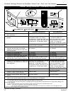
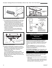
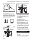
NOTE: Verify the two relief doors (located on top of
the firebox) are properly seated on the gasket. The
doors sit flush on the gasket, and should lift easily
from the seal around the opening.
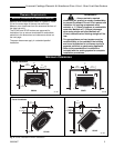
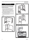
Unpack the Log Set and Rear Shroud
Cut the shipping straps and remove the Rear Shroud
carton. (Fig. 11) Do not remove the firebox from the
shipping pallet yet. The Log Set is packed inside the
firebox. The Glass Panel must first be removed to
install the Log Set within the firebox.
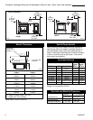
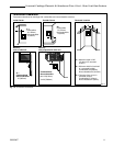
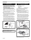
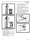
1. Pivot the two latches at the top corners to disengage
the latches from the retainer posts at the top of the
firebox. (Fig. 12) Lift the glass frame assembly off
the front and place it out of the way on a flat, pad-
ded surface such as a counter protected by a towel.
The glass panel will not be replaced until the entire
installation is complete and the pilot has been lit.
2. Remove the Log Set from its packaging and set the
pieces aside. Remove any packing material from the
firebox.
3. Remove the Rear Shroud from the shipping carton.
Packed
Log Set
Rear Shroud
Carton
ST390
Fig. 11 Firebox as shipped.
Failure to position the parts in
accordance with these diagrams or
failure to use only parts specifically
approved for use with this heater may result in
property damage or personal injury.
This heater and components are heavy. Have
help available for assembly.
WARNING
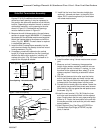
Firebox Preparation
Check the Rating Plate attached by a steel cable to the
firebox, to confirm that you have the appropriate firebox
for the type of fuel to be used. The PDV20/SDVR may
be converted from one gas to another using the appro-
priate Fuel Conversion Kit listed on page 43.
Fig. 12 Pivot the locking latches to release the glass frame.
ST391