


3
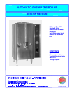
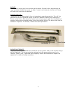
ASSEMBLY: The four legs and vent cap drain are packed separately with the water
boiler. Install legs by tilting the water boiler on its side and screwing the legs into the
leg supports until hand tight. Carefully right the unit and install in its permanent
location, being sure to leave at least 6” on the right side of the water boiler for access
to the control box. Level the unit by adjusting the bottom pad of the legs. Place the
vent cap into the recess in the top of the unit. Mount the faucet assembly onto the
shank in upright position.
INSTALLATION AND OPERATING INSTRUCTION:
PRE-INSTALLATION INSTRUCTIONS: The installation of your water boiler must be made
by a licensed plumber and the installation must conform with State and Local Codes or
in absence of Local Codes, with the National Fuel Gas Code ANSI Z223.1 a latest
version.
AIR SUPPLY AND VENTILATION: Adequate ventilation and air supply must be provided
in order for the water boiler to operate properly and efficiently. The area in front of and
above the unit must be clear to avoid any obstruction of flow of combustion and
ventilation air. DO NOT under any circumstances, connect the water boiler flue directly
to a building exhaust system or place the flue outlet directly into the plenum of the
exhaust hood as it will adversely affect the gas combustion of the water boiler.
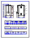
CLEARANCES: Your water boiler is design certified to use on combustible floors. The
side and back clearances for combustible constructions are as follows: 6 inches from
side and 8 inches from back. The water boiler must be installed with 4 inch high legs
provided.
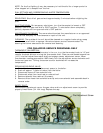
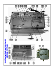
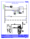
GAS CONNECTION: Before connecting the water boiler to the gas line Examine the gas
specification label attached to the right side panel to be certain that the type of gas for
which the unit is equipped is the same as the gas supply. A 3/8 NPT gas connection is
needed to connect the unit to the gas line. An accessible manual shut-off valve must be
installed in the gas supply line in case of an emergency. The gas supply pipe must be
sized to accommodate all the gas fired equipment that may be connected to it. Check
with your local Gas Company as to proper pipe size. Sealant on all pipe joints must be
resistive to propane gas. Before attempting to light the water boiler, check all joints for
gas tightness using a soap and water solution.
WATER CONNECTION: The unit is supplied with ¼” flare fitting. Connect the copper
tubing with the flare fitting to the water connection at the rear of the machine. The
water line must have a shut-off valve (supplied by a plumber) to a cold water supply.
Water pressure should be 20 lbs. minimum for proper operation.
NOTE: Connecting the unit to a warm water supply will speed by heating and recovery
time.
To turn on the water supply valve plug the line cord into a dedicated 120V grounded
receptacle (NEMA 5-15R). The water will start entering the unit and automatically fill it
to capacity.
PRIMING OR INITIAL FILLING: Turn on the water supply. The unit fills at the rate of 1
gallon per minute. When the water level becomes visible in the sight gauge, turn the
thermostat knob to the ON position. The boiler will now automatically fill to capacity
and heat the water.
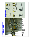
LIGHTING AND ADJUSTMENT: Water must be visible in the sight glass before lighting to
pilot. Turn the thermostat knob to its lowest position. Turn gas cock dial to PILOT
position. Depress gas cock dial and light pilot with a long lighted match through the
opening located on the bottom of the urn. Hold in depressed position for approximately
30 sec. or until pilot remains lit when dial is released.