9
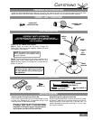
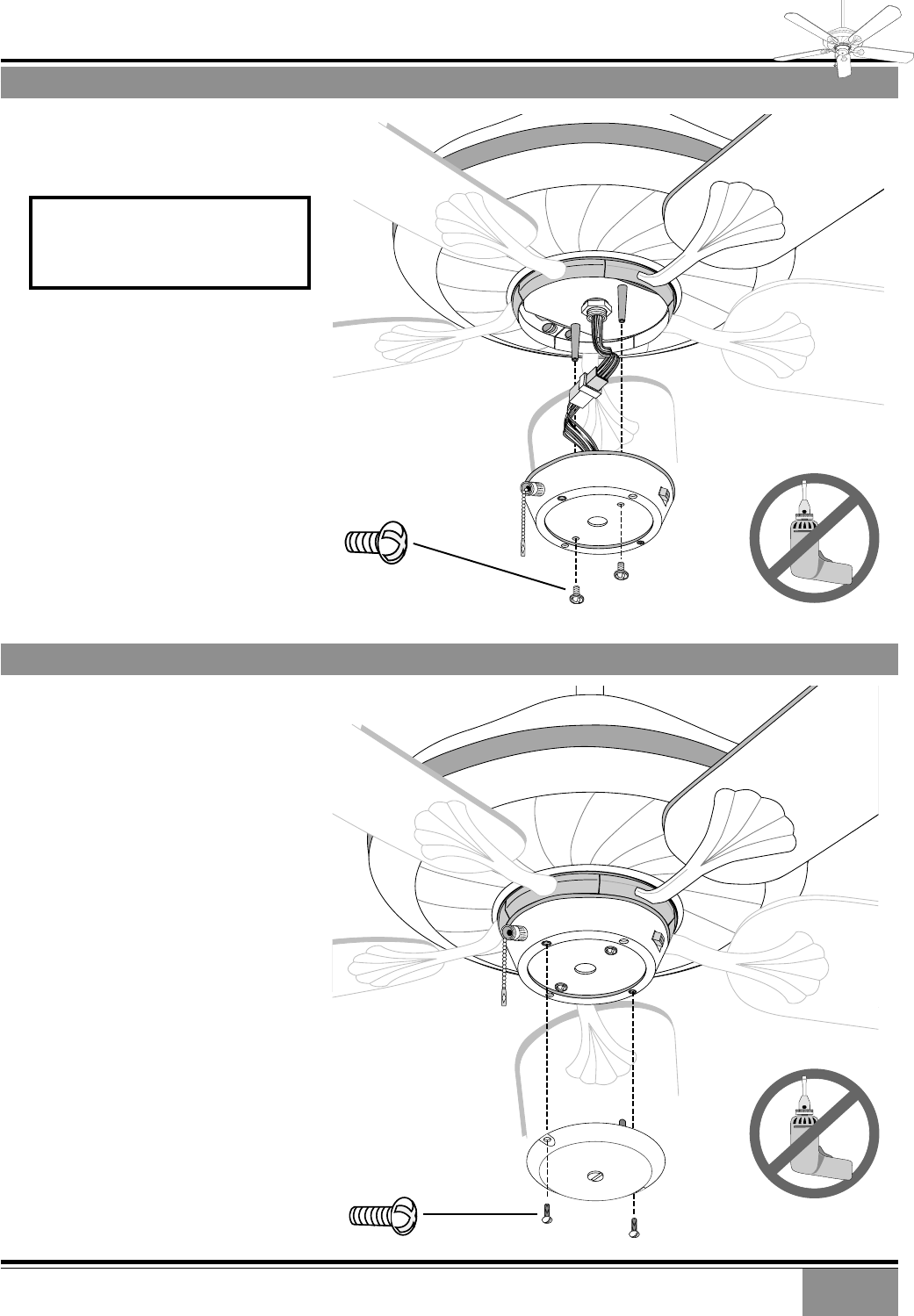
INSTALLING THE SWITCH HOUSING ASSEMBLY
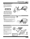
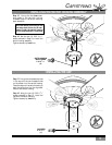
Step 17. Line up the two clearance holes
in the cap with the two threaded holes
on the raised rim of the switch housing.
Press the cap onto the switch housing to
seat the guide pins into the alignment
holes of the switch housing.
Step 18. Using the two (2) 8-32 X
3
/8″
screws removed in Step 13, install the
cap onto the switch housing.
Tighten securely by hand only.
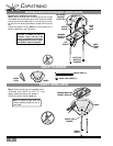
INSTALLING THE CAP
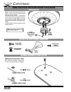
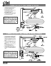
Step 15. Line up the two inner clear-
ance holes in the cap with the two
threaded holes in the switch mounting
plate standoffs.
Step 16. Use the two (2) 5-32 X
9
/32″
screws removed in Step 8 to install the
switch housing assembly.
Tighten securely by hand only.
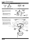
CAP SCREW
8-32 X
3
/8″
(2)
SWITCH HOUSING
MOUNT SCREW
5-32 X
9
/32″
(2)
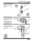
CAUTION! Before continuing to the
next step check that a wire or com-
ponent inside the switch housing
will not be pinched as it is installed.
Casablanca
CAPISTRANO


