


6
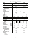
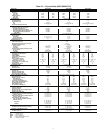
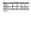
Table 1C — Physical Data (48ZG,ZN075-105)
BASE UNIT 48ZG,ZN075 48ZG,ZN090 48ZG,ZN105
NOMINAL CAPACITY (tons) 75 90 105
OPERATING WEIGHT (lb)
Base Unit without Economizer
Low Heat/High Heat 10,270/10,445 10,480/10,655 11,210/11,385
With Economizer
Low Heat/High Heat 10,800/10,975 11,010/11,185 11,740/11,915
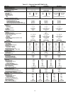
COMPRESSOR Semi-Hermetic
Number 22 4
Circuit (No. Cyl) A (6) B (6) A (6) B (6) A1 (6), A2 (4) B1 (6), B2 (4)
Model 06E -275 -299 -299 -299 -275, -250 -275, -250
Oil Charge (pints) 19 19 19 19 19, 14 19, 14
Capacity Steps (%)
CV 43,100 50,100 50,100
VAV 14,29,43,51,66,86,100 17,33,50,67,83,100 20,30,40,50,60,60,70,80,80,90,100
Number of Refrigerant Circuits 22 2
REFRIGERANT R-22
Operating Charge (lb), Ckt 1/Ckt 2
Standard Evaporator Coil 70.5/64.5 64.0/64.0 68.0/68.0
Standard Evaporator with HGBP 73.5/64.5 67.0/64.0 71.0/68.0
Alternate High-Capacity Evaporator Coil 83.0/75.0 76.0/76.0 79.5/79.5
Alternate High-Capacity Evaporator with HGBP 86.0/75.0 79.0/76.0 82.5/79.5
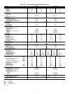
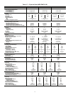
CONDENSER COILS
3
/
8
-in. Tube Diameter
Quantity 44 4
Rows...Fins/in.
Aluminum 3...17.0 3...17.0 3...17.0
Copper (Optional) 3...15.7 3...15.7 3...15.7
Fin Type Double Wavy Lanced, Sine-wave Lanced, Sine-wave
Tube Type Smooth Cross-Hatched Cross-Hatched
Total Face Area (sq ft) 108.4 108.4 108.4
EVAPORATOR COILS
Quantity 2
Total Face Area (sq ft) 61.5
Refrigerant Feed Device...No. per Circuit TXV...2
Standard Evaporator Coils
1
/
2
in. Tube Dia
3
/
8
in. Tube Dia
3
/
8
in. Tube Dia
Rows...Fins/in. 4...17.0 4...17.0 4...17.0
Fin Type Double Wavy Lanced, Sine Wave Lanced, Sine Wave
Tube Type Smooth Cross Hatched Cross Hatched
Alternate, High-Capacity Evaporator Coils
1
/
2
in. Tube Dia
Rows...Fins/in. 6...16 6...16 6...16
Fin Type Double Wavy Double Wavy Double Wavy
Tube Type Cross Hatched Cross Hatched Cross Hatched
HEATING SECTION Low Heat High Heat Low Heat High Heat Low Heat High Heat
Number of Heat Exchangers 2323 2 3
Input (MBtuh) 650 975 650 975 650 975
Output (MBtuh) 527 790 527 790 527 790
Temperature Rise Range (F) 10-40 20-50 10-40 20-50 10-40 20-50
Efficiency (%) 81 81 81 81 81 81
Burner Orifice Diameter
Quantity (in. ...drill no.) 14 (.1285...30) 21 (.1285...30) 14 (.1285...30) 21 (.1285...30) 14 (.1285...30) 21 (.1285...30)
Manifold Pressure (in. wg) 3.3 3.3 3.3 3.3 3.3 3.3
Line Pressure (in. wg) (Min...Max) 5.0...13.0 5.0...13.0 5.0...13.0 5.0...13.0 5.0...13.0 5.0...13.0
Number of Gas Valves 2323 2 3
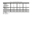
CONDENSER FAN Propeller Type
Quantity...Diameter (in.) 5...30 6...30 6...30
Nominal Cfm 50,000 60,000 60,000
Motor Hp (ea)...rpm 1.0...1140 1.0...1140 1.0...1140
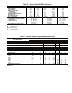
STANDARD SUPPLY FAN Forward Curved Centrifugal 36 x 30 in.
Nominal Cfm 24,500 29,750 35,000
Maximum Allowable Cfm 30,000 34,000 40,000
Maximum Allowable Rpm 670 670 670
Shaft Diameter at Pulley (in.) 1
11
/
16
1
11
/
16
1
11
/
16
STANDARD SUPPLY-FAN MOTOR AND DRIVE (Any motor available on any unit)
Motor Hp 30 40 50 60
Motor Frame Size S268T S324T S36T S364T
Efficiency at Full Load (%)
High Efficiency 92.4 93.0 93.0 93.6
Premium Efficiency 93.6 94.5 94.5 95.4
Fan Pulley Pitch Diameter (in.) 18.5 18.5 18.5 18.5
Motor Pulley Pitch Diameter (in.) 5.3 5.7 6.5 7.1
Resulting Fan Rpm 501 539 615 672
Belts Quantity...Type 3...5VX1320 4...5VX1320 4...5VX1320 4...5VX1320
Center Distance Range (in.) 47.88-45.01 47.64-44.76 47.42-44.52 47.42-44.52
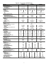
ALTERNATE, AIRFOIL FAN Airfoil
Nominal Airflow (cfm) 24,500 29,750 35,000
Maximum Allowable Airflow (cfm) 30,000 34,000 40,000
Maximum Allowable Wheel Speed (rpm) 1846 1846 1846
Shaft Diameter at Pulley (in.) 2
11
/
16
2
11
/
16
2
11
/
16
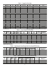
ALTERNATE SUPPLY-FAN MOTOR AND DRIVE (Any motor available on any unit)
Motor Hp 30 40 50 60 75
Motor Frame Size S268T S324T S36T S364T 365T
Efficiency at Full Load (%)
High Efficiency 92.4 93.0 93.0 93.6 94.1
Premium Efficiency 93.6 94.5 94.5 95.4 95.4
Fan Pulley Pitch Diameter (in.) 9.7 10.2 8.9 8.9 10.8
Motor Pulley Pitch Diameter (in.) 7.5 8.7 8.1 8.7 11.1
Resulting Fan Rpm 1353 1493 1593 1711 1799
Belts Quantity...Type 2...5VX1150 2...5VX1180 3...5VX1150 3...5VX1150 3...5VX1230
Center Distance Range (in.) 42.96-45.82 42.96-45.57 42.96-45.57 42.45-45.35 42.45-45.35