37
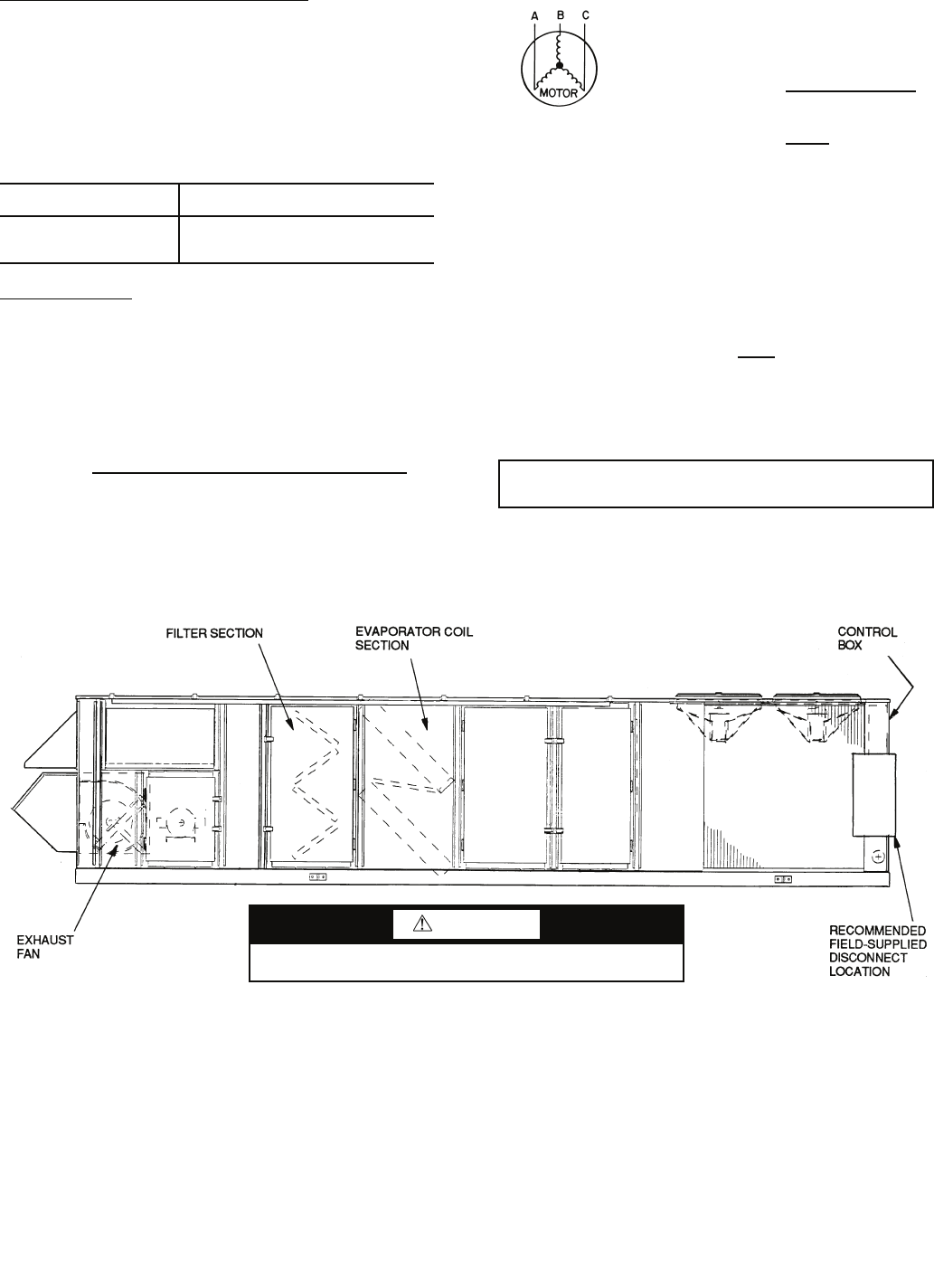
Units with Factory-Installed Disconnect
— The factory-
installed disconnect is an interlocking, door-type. The discon-
nect handle locks the door when it is in the ON position. The
disconnect handle must be in the OFF position to open the con-
trol box door. The disconnect is located in a separate control
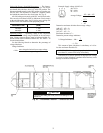
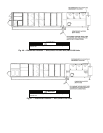
box behind the control box door for all units. See Fig. 43.
All field wiring must comply with NEC and all local codes.
Wire must be sized based on MCA (Minimum Circuit Amps)
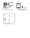
on the unit informative plate. See Fig. 44 for power wiring con-
nections to the unit disconnect and equipment ground.
Operating Voltage
— Operating voltage to the compressor
must be within the voltage range indicated on the unit name-
plate. Voltages between phases must be balanced within 2%,
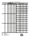
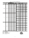
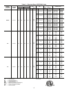
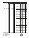
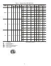
and the current must be balanced within 10%. See Tables 7-16
for unit electrical data.
Use the following formula to determine the percentage of
voltage imbalance.
Voltage Imbalance
Example: Supply voltage is 460-3-60.
AB = 452 v
BC = 464 v
AC = 455 v
Determine maximum deviation from average voltage:
(AB) 457 – 452 = 5 v
(BC) 464 – 457 = 7 v
(AC) 457 – 455 = 2 v
Maximum deviation is 7 v.
Determine percent voltage imbalance:
= 1.53%
This amount of phase imbalance is satisfactory as it is be-
low the maximum allowable 2%.
Unit failure as a result of operation on improper line voltage
or excessive phase imbalance constitutes abuse and may cause
damage to electrical components.
DISCONNECT SIZE
QUANTITY...MAXIMUM WIRE SIZE
(MCM)
200 Amps
400 Amps
600 Amps
1...300
1...600
2...600
= 100 x
max voltage deviation from average voltage
average voltage
Average Voltage =
455 + 464 + 455
3
=
1371
3
= 457
% Voltage Imbalance = 100 x
7
457
IMPORTANT: If the supply voltage phase imbalance is
more than 2%, contact local utility immediately.
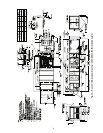
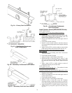
Fig. 39 — Disconnect Location — Size 030-050 Units
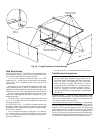
CAUTION
Use care when drilling into corner post to avoid damage to con-
denser coil.


