


3
Thermostat Installation —
Begin the thermostat in-
stallation by determining where the thermostat will be located.
In most cases, this will be pre-determined by the building
plans.
Locate the thermostat on an interior wall, about 5 ft from the
ground. The thermostat should be located away from direct
sunlight, drafts, or interior heat sources which may influence
temperature readings.
The thermostat may also be mounted in a remote location
with the use of an optional remote room sensor. Refer to the
specific thermostat information for more details on thermostat
installation.
Wiring Connections
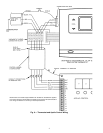
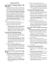
WIRE APOLLO CONTROL TO THERMOSTAT — Wire
each thermostat to its respective Apollo control as shown in
Fig. 6. Make wiring connections at the wiring connector board
of the thermostat.
WIRE THERMOSTAT TO COMMUNICATION BUS —
The thermostat is connected to the communication bus through
the thermostat wiring connection block. Connect the black, red,
and green wires from the communication bus to the thermostat
wiring connection block. See Fig. 6. To connect other devices
to the communication bus, refer to the application manual for
that device.
Provide Power To Apollo Control —
After the wir-
ing has been completed, provide power to the Apollo control.
Once power has been provided, the Apollo control will power
the thermostat. The heating (if applicable) and/or cooling set
points will appear on the thermostat display screen. The ther-
mostat is now ready to be programmed. If the display is blank
or blinking, recheck the wiring connections between the ther-
mostat and Apollo control.
OPERATION
There are 3 system switches which are used to control oper-
ation at the thermostat: Heat, Cool, and Fan. The Heat and
Cool switches can be set to either AUTO. or OFF position. The
Fan switch can be set to either AUTO or ON position. When
the fan is running, the FAN indicator will be shown on the ther-
mostat display screen. When Cooling mode is energized, the
COOL indicator will be shown on the thermostat display
screen. When Heating mode is energized, the HEAT indicator
will be shown on the thermostat display screen. When the
second stage of heating or cooling is energized, a decimal point
is displayed between the heating and cooling set points.
AUTO. Fan Mode —
The fan will energize any time the
system energizes heating or cooling. The only exception is
when the thermostat controls a gas heating rooftop unit. In this
application, the thermostat will allow the rooftop unit to control
the fan during Heating mode, and the fan will run in Cooling
mode.
ON Fan Mode —
The fan will operate continuously dur-
ing the occupied mode. In unoccupied mode, the fan will only
operate when a system mode is energized.
AUTO. Heating Mode —
When the Heat switch is set to
AUTO. position, the Apollo control will energize heating when
the heating demand is 1.5° F or greater. The second stage of
heating will energize when the demand becomes 2.0° F or
greater.
OFF Heating Mode —
When the Heat switch is set to
OFF position, the Apollo control will not allow the rooftop unit
to energize heating.
AUTO. Cooling Mode —
When the Cool switch is set
to AUTO. position, the Apollo control will energize cooling
when the cooling demand is 1.5° F or greater. The second stage
of cooling will energize when the demand becomes 2.0° F or
greater.
OFF Cooling Mode —
When the Cool switch is set to
OFF position, the Apollo control will not allow the rooftop unit
to energize cooling.
Temperature Trend Staging —
When the Tempera-
ture Trend Staging option has been configured at the thermo-
stat, the thermostat tracks the temperatures at regular intervals
in each cooling or heating mode. As long as the space tempera-
ture is improving, the Apollo control will not allow the second
stage to be energized. If the space temperature stays the same
or the demand becomes greater, the second stage will energize.
Heating Lockout —
When the heating lockout tempera-
ture set point has been configured, and the heating lockout op-
tion has been configured to ON, the Apollo control will not al-
low heating to energize when the outdoor-air temperature rises
above the heating lockout set point.
Cooling Lockout —
When the cooling lockout tempera-
ture set point has been configured, and the cooling lockout op-
tion has been configured to ON, the Apollo control will not al-
low cooling to energize when the outdoor-air temperature
drops below the cooling lockout set point.
Time-Delay Relay —
The thermostat and the Apollo
control utilize a 5-minute time delay between the different
modes of operation for the rooftop unit. When a mode of oper-
ation is deenergized, another mode cannot begin for 5 minutes.
Electric shock can cause injury or death. Ensure power to
the rooftop unit has been disconnected, before wiring.