


2
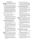
APOLLO CONTROL — The Apollo control (see Fig. 4) has
the following features:
• serves as interface between thermostat, Carrier rooftop
unit, and any external field-supplied sensors
• powered by 24 vac/10 va; supplies thermostat with
10 vdc. This power is supplied by the Carrier rooftop
unit.
The Apollo control must be used in conjunction with a
Carrier 33CSTM(T)-01 or 33CSVM(T)-XX master thermo-
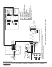
stat. Figure 5 shows the Apollo control factory-installed in a
rooftop unit.
INSTALLATION
Wiring Requirements —
The wiring requirements for
the TEMP System are:
THERMOSTAT TO THERMOSTAT COMMUNICATION
BUS — Use field-supplied, 18 gage, 3-conductor, shielded,
stranded wire, color coded (red, black, green), plenum rated (if
required by code). Be sure wire is long enough to run from
thermostat to thermostat in daisy-chain configuration.
THERMOSTAT TO APOLLO CONTROL — Use field-
supplied, 18 gage, 5-conductor, shielded, stranded wire,
color-coded (red, white, blue, yellow, green), plenum rated (if
required by code). Be sure wire is long enough to run from
thermostat to the Apollo control. The Apollo control is easily
accessible in the Carrier rooftop unit. It is found in the unit
control box.
Factory-supplied power required by each Apollo control is
24 vac/10 va. Typical wiring is 18-gage thermostat wire. Power
to the Apollo control may be wired to the Carrier rooftop unit
transformer if transformer is of sufficient va capacity. Other-
wise, a dedicated transformer has been factory provided. The
maximum load of a relay contact is 24 vac, 1 amp. A short in
the field wiring or Carrier rooftop unit will cause non-warranty
damage to the relay board. Test wiring before attaching to
Apollo control.
Call your local Carrier representative for more information
about wiring the Apollo control as needed.
IMPORTANT: Do not run the thermostat communication
bus and the control wire in the same conduit for more than
5 ft. Never run wires near any cable carrying AC voltage.
For further wiring information, consult your local Carrier
distributor.
*Where “XX” will be “04,” “16,” or “32.”
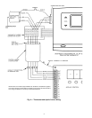
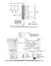
Fig. 2 — TEMP System Communication
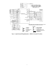
Fig. 3 — TEMP System Thermostat
(With Timeclock Shown)
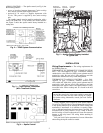
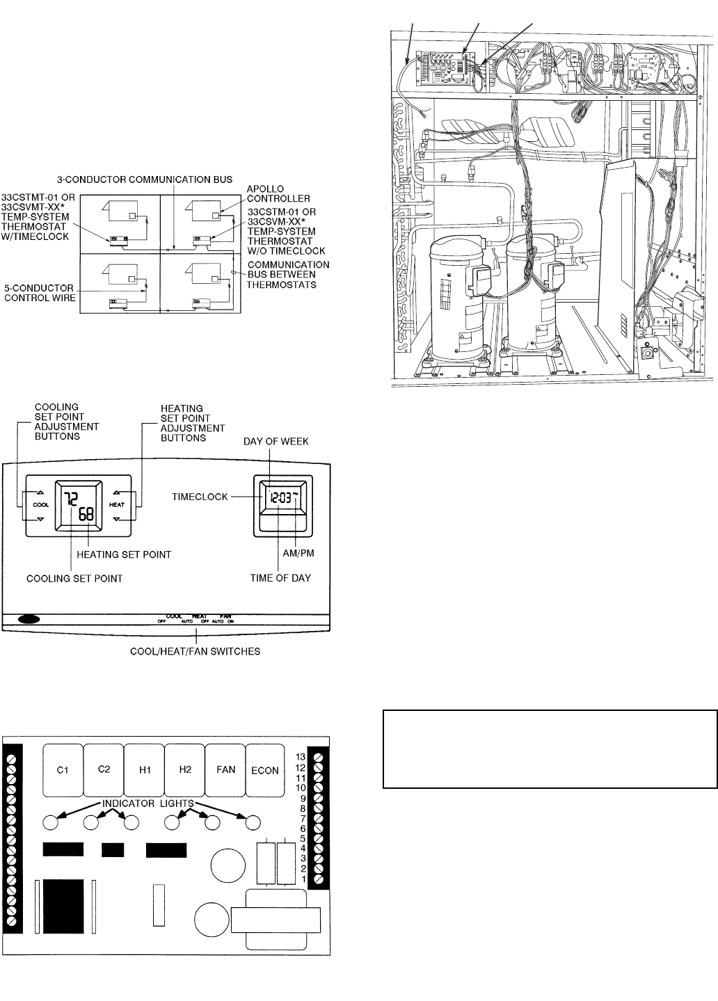
NOTE: The indicator lights verify each mode of operation.
Fig. 4 — Apollo Control
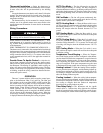
CONTROL
WIRING
APOLLO
CONTROL
WIRING TO
THERMOSTAT
Fig. 5 — Apollo Control Factory-Installed
In Typical Unit