


41
Lubrication
COMPRESSORS — Each compressor is charged with the
correct amount of oil at the factory.
FAN-MOTOR BEARINGS — Fan-motor bearings are of
the permanently lubricated type. No further lubrication is re-
quired
.
No lubrication of condenser or evaporator fan motors is
required.
Manual Outdoor-Air Damper —
If outdoor-air damper
blade adjustment is required, see Manual Outdoor-Air Damper
section on page 12.
Economizer Adjustment —
Refer to Optional Econo-
mizer sections on pages 13 and 15.
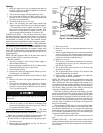
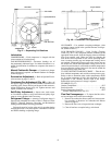
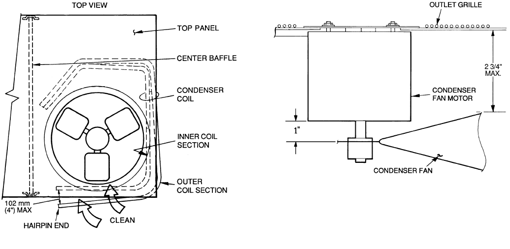
Condenser Fan Adjustment (Fig. 48) —
Shut off
unit power supply and tag disconnect. Remove condenser-fan
assembly (grille, motor, and fan) and loosen fan hub setscrews.
Adjust fan height as shown in Fig. 48. Tighten setscrews and
replace condenser-fan assembly.
Belt/Pulley Adjustment —
Inspect once each season,
or if conditions warrant to verify belt tension and pulley align-
ment are correct. Replace belt if necessary.
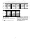
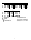
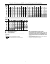
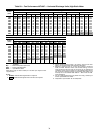
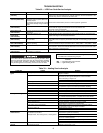
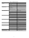
Refrigerant Charge —
Amount of refrigerant charge is
listed on unit nameplate (also refer to Table 1). Refer to Carrier
GTAC2-5 Charging. Recovery, Recycling, and Reclamation
training manual and the following procedures.
Unit panels must be in place when unit is operating during
charging procedure. Unit must operate a minimum of 10 min-
utes before checking or adjusting charge.
NO CHARGE — Use standard evacuating techniques. After
evacuating system, weigh in the specified amount of refriger-
ant. (Refer to Table 1.)
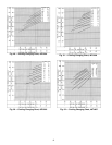
LOW-CHARGE COOLING — Using Cooling Charging
Charts, Fig. 49-52, vary refrigerant until the conditions of the
appropriate chart are met. Note the charging charts are different
from type normally used. Charts are based on charging the
units to the correct superheat for the various operating condi-
tions. Accurate pressure gage and temperature sensing device
are required. Connect the pressure gage to the service port on
the suction line. Mount the temperature sensing device on the
suction line and insulate it so that outdoor ambient temperature
does not affect the reading. Indoor-air cfm must be within the
normal operating range of the unit.
TO USE COOLING CHARGING CHART — Take the out-
door ambient temperature and read the suction pressure gage.
Refer to chart to determine what suction temperature should
be. If suction temperature is high, add refrigerant. If suction
temperature is low, carefully recover some of the charge.
Recheck the suction pressure as charge is adjusted.
EXAMPLE: (Fig. 51)
Outdoor Temperature. . . . . . . . . . . . . . . . . . . . . . . . . . . . . . .85 F
Suction Pressure. . . . . . . . . . . . . . . . . . . . . . . . . . . . . . . . 80 psig
Suction Temperature should be. . . . . . . . . . . . . . . . . . . . . . .68 F
(Suction Temperature may vary 5 F.)
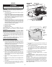
Flue Gas Passageways —
To inspect the flue collec-
tor box and upper areas of the heat exchanger:
1. Remove the combustion blower wheel and motor assem-
bly according to directions in Combustion-Air Blower
section on page 43.
2. Remove the flue cover to inspect the heat exchanger.
3. Clean all surfaces as required using a wire brush.
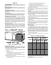
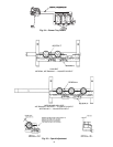
Fig. 47 — Separating Coil Sections
Fig. 48 — Condenser-Fan Adjustment