


38
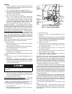
Heating
1. Purge gas supply line of air by opening union ahead of
gas valve. If gas odor is detected, tighten union and wait
5 minutes before proceeding.
2. Turn on electrical supply and open manual gas valve.
3. Set system switch selector at HEAT position and fan
switch at AUTO. or ON position. Set heating temperature
lever above room temperature.
4. The induced-draft motor will start.
5. After a call for heating, the main burners should light
within 5 seconds. If the burner does not light, then there is
a 22-second delay before another 5-second try. If the
burner still does not light, the time delay is repeated. If the
burner does not light within 15 minutes, there is a lock-
out. To reset the control, break the 24 v power to W1.
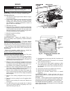
ADJUST GAS INPUT — The gas input to the unit is deter-
mined by measuring the gas flow at the meter or by measuring
the manifold pressure. Measuring the gas flow at the meter is
recommended for natural gas units. The manifold pressure
must be measured to determine the input of propane gas units.
Measure Gas Flow (Natural Gas Units)
— Minor adjustment
to the gas flow can be made by changing the manifold pressure.
The manifold pressure must be maintained between 3.4 and
3.6 in. wg. If larger adjustments are required, change main
burner orifices following the recommendations of national and
local codes. Unit must be operating with both W1 and W2 en-
ergized (high-fire).
NOTE: All other appliances that use the same meter must be
turned off when gas flow is measured at the meter.
Proceed as follows:
1. Turn off gas supply to unit. Turn off electric supply to
unit and install lockout tag.
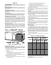
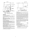
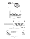
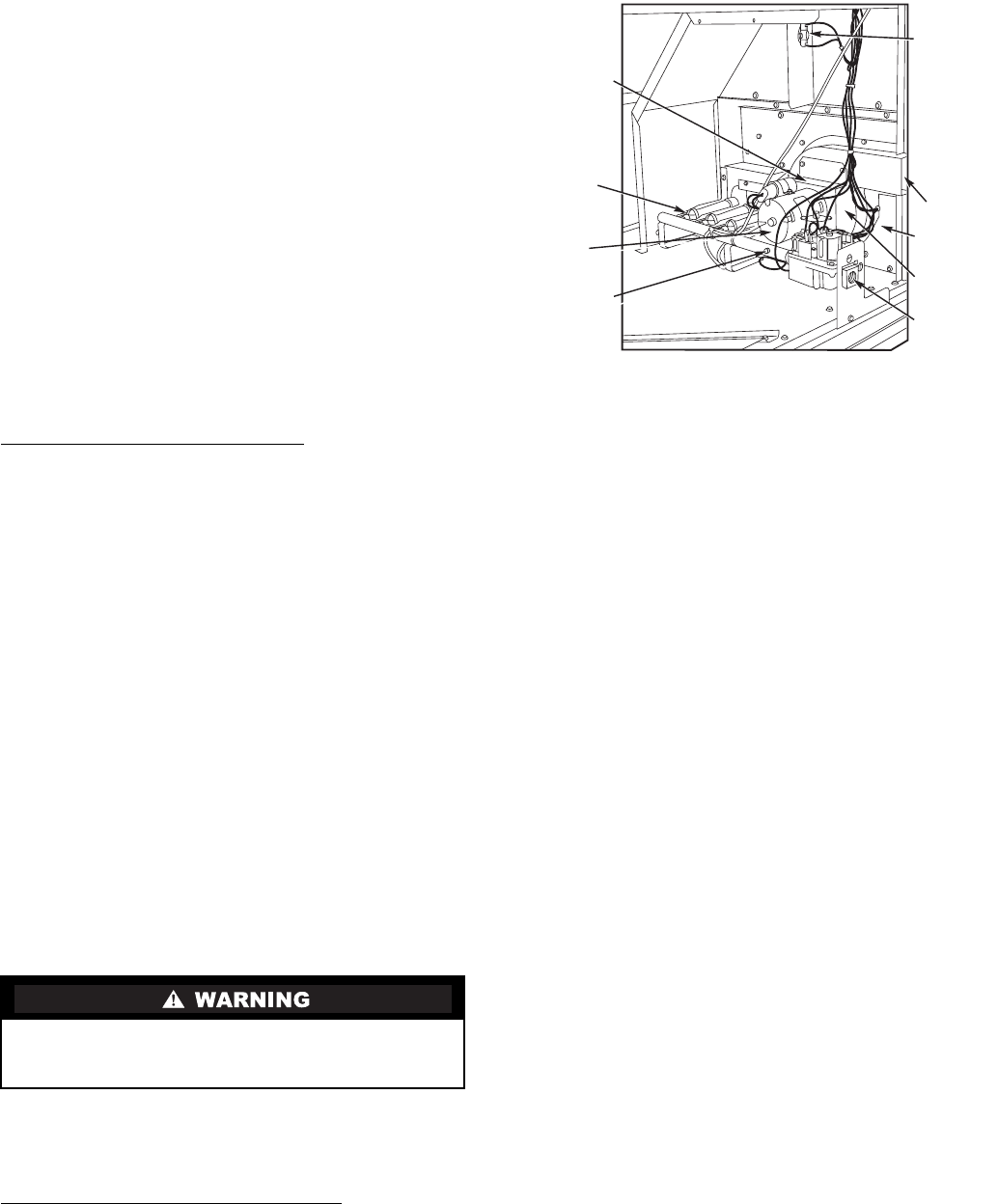
2. Remove pipe plug on manifold (see Fig. 44) then connect
manometer at this point. Turn on gas to unit.
3. Turn on electrical power.
4. Energize W1, and/or W2 at thermostat. Ensure gas valve,
if 2-stage style, is in “High Fire.”
Observe manifold pressure and proceed as follows to adjust
gas input:
1. Remove cover screw over regulator adjustment screw on
gas valve.
2. Turn regulator adjustment screw clockwise to increase
gas input, or turn regulator adjustment screw counter-
clockwise to decrease input. Manifold pressure must be
3.5 in. wg while in high fire.
3. Replace cover screw cap on gas valve.
4. Turn off gas supply to unit. Remove manometer from
pressure tap and replace pipe plug on gas valve. Turn on
gas to unit and check for leaks.
Measure Manifold Pressure (Propane Units)
— The main
burner orifices on a propane gas unit are sized for the unit rated
input when the manifold pressure reading is 3.5 in. wg.
Ensure unit is operating in High-Fire operation mode (W1
and W2 energized) before adjusting manifold pressure.
Proceed as follows to adjust gas input on a propane gas unit:
1. Turn off gas to unit.
2. Remove pipe plug on manifold (see Fig. 44), then con-
nect manometer at this point.
3. Turn on gas to unit.
4. Remove cover screw over regulator adjustment screw on
gas valve.
5. Adjust regulator adjustment screw to the correct manifold
pressure, 3.5 in wg. Turn adjusting screw clockwise to in-
crease manifold pressure, or turn adjusting screw counter-
clockwise to decrease manifold pressure.
6. Replace cover screw.
7. Turn off gas to unit. Remove manometer from pressure
tap. Replace pipe plug on gas valve, then turn on gas to
unit. Check for gas leaks.
8. The evaporator-fan motor will turn on 45 seconds after
the burners are ignited.
9. The evaporator-fan motor will turn off 45 seconds after
thermostat temperature is satisfied.
10. Adjust airflow to obtain a temperature rise within the
range specified on the unit nameplate.
NOTE: The default value for the evaporator-fan motor ON/
OFF delay is 45 seconds. The Integrated Gas Unit Controller
(IGC) modifies this value when abnormal limit switch cycles
occur. Based upon unit operating conditions, the ON delay can
be reduced to 0 seconds and the OFF delay can be extended to
180 seconds. When one flash of the LED is observed, the
evaporator-fan ON/OFF delay has been modified.
If the limit switch trips at the start of the heating cycle dur-
ing the evaporator ON delay, the time period of the ON delay
for the next cycle will be 5 seconds less than the time at which
the switch tripped. (Example: If the limit switch trips at 30 sec-
onds, the evaporator-fan ON delay for the next cycle will occur
at 25 seconds.) To prevent short-cycling, a 5-second reduction
will only occur if a minimum of 10 minutes has elapsed since
the last call for heating.
The evaporator-fan OFF delay can also be modified. Once
the call for heating has ended, there is a 10-minute period dur-
ing which the modification can occur. If the limit switch trips
during this period, the evaporator-fan OFF delay will increase
by 15 seconds. A maximum of 9 trips can occur, extending the
evaporator-fan OFF delay to 180 seconds.
To restore the original default value, reset the power to the
unit.
TO SHUT OFF UNIT — Set system selector switch at OFF
position. Resetting heating selector lever below room tempera-
ture will shut unit off until space temperature falls below ther-
mostat setting.
Unsafe operation of the unit may result if manifold pres-
sure is outside this range. Personal injury or unit damage
may result.
INDUCED-
DRAFT
MOTOR
MOUNTING
PLATE
VESTIBULE
PLATE
FLUE
EXHAUST
ROLLOUT
SWITCH
BLOWER
HOUSING
GAS
VALVE
BURNER
SECTION
MANIFOLD
PRESSURE
TRAP
(PIPE
PLUG)
INDUCED-
DRAFT
MOTOR
Fig. 44 — Burner Section Details