


33
Heating/Cooling Thermostat Type
— Switch 3 provides se-
lection of thermostat type. Heat pump or heat/cool thermostats
can be selected. Select OFF for heat/cool thermostats. When in
heat/cool mode, Y1 is used for cooling stage 1, Y2 is used for
cooling stage 2, W1 is used for heating stage 1 and O/W2 is
used for heating stage 2. Select ON for heat pump thermostats.
In heat pump mode, Y1 used is for compressor stage 1, Y2 is
used for compressor stage 2, W1 is used for heating stage 3 or
emergency heat, and O/W2 is used for reversing valve (heating
or cooling) depending upon switch 4 setting.
O/B Thermostat Type
— Switch 4 provides selection for heat
pump O/B thermostats. O is cooling output. B is heating out-
put. Select ON for thermostats with O output. Select OFF for
thermostats with B output.
Dehumidification Fan Mode
— Switch 5 provides selection
of normal or dehumidification fan mode. Select OFF for dehu-
midification mode. The fan speed relay will remain OFF dur-
ing cooling stage 2. Select ON for normal mode. The fan speed
relay will turn on during cooling stage 2 in normal mode.
Output
— Switch 6 provides selection for DDC operation. If
set to DDC output at EH2, the EH2 terminal will continuously
output the last fault code of the controller. If the control is set to
EH2 normal, then the EH2 will operate as standard electric
heat output. Set the switch to ON to set the EH2 to normal. Set
the switch to OFF to set the DDC output at EH2.
Boilerless Operation
— Switch 7 provides selection of boiler-
less operation and works in conjunction with switch 8. In boil-
erless operation mode, only the compressor is used for heating
when FP1 is above the boilerless changeover temperature set
by switch 8 below. Select ON for normal operation or select
OFF for boilerless operation.
Boilerless Changeover Temperature
— Switch 8 on S1 pro-
vides selection of boilerless changeover temperature set point.
Select OFF for set point of 50 F or select ON for set point of
40 F.
If switch 8 is set for 50 F, then the compressor will be used
for heating as long as the FP1 is above 50 F. The compressor
will not be used for heating when the FP1 is below 50 F and the
compressor will operates in emergency heat mode, staging on
EH1 and EH2 to provide heat. If a thermal switch is being used
instead of the FP1 thermistor, only the compressor will be used
for heating mode when the FP1 terminals are closed. If the FP1
terminals are open, the compressor is not used and the control
goes into emergency heat mode.
DIP SWITCH BANK 2 (S2) — This set of DIP switches is
used to configure accessory relay options.
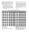
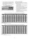
Switches 1 to 3
— These DIP switches provide selection of
Accessory 1 relay options. See Table 14 for DIP switch
combinations.
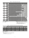
Switches 4 to 6
— These DIP switches provide selection of
Accessory 2 relay options. See Table 15 for DIP switch
combinations.
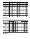
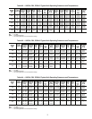
Table 14 — DIP Switch Block S2 —
Accessory 1 Relay Options
LEGEND
NOTE: All other DIP switch combinations are invalid.
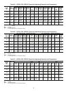
Table 15 — DIP Switch Block S2 —
Accessory 2 Relay Options
LEGEND
NOTE: All other switch combinations are invalid.
Auto Dehumidification Mode or High Fan Mode — Switch 7
provides selection of auto dehumidification fan mode or high
fan mode. In auto dehumidification fan mode, the fan speed
relay will remain off during cooling stage 2 if terminal H is
active. In high fan mode, the fan enable and fan speed relays will
turn on when terminal H is active. Set the switch to ON for auto
dehumidification fan mode or to OFF for high fan mode.
Factory Setting
— Switch 8 is set to ON. Do not change the
switch to OFF unless instructed to do so by the factory.
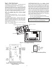
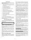
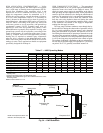
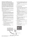
Units with Modulating Hot Water Reheat
(HWR) Option —
A heat pump equipped with hot water
reheat (HWR) can operate in three modes: cooling, cooling
with reheat, and heating. The cooling and heating modes are
like any other water source heat pump. The reversing valve
("O" signal) is energized in cooling, along with the compressor
contactor(s) and blower relay. In the heating mode, the revers-
ing valve is deenergized. Almost any thermostat will activate
the heat pump in heating or cooling modes. The Deluxe D
microprocessor board, which is standard with the HWR
option, will accept either heat pump (Y,O) thermostats or non-
heat pump (Y,W) thermostats.
The reheat mode requires either a separate humidistat/
dehumidistat or a thermostat that has an integrated dehumidifi-
cation function for activation. The Deluxe D board is config-
ured to work with either a humidistat or dehumidistat input to
terminal “H” (DIP switch settings for the Deluxe D board are
shown in Table 16). Upon receiving an “H” input, the Deluxe
D board will activate the cooling mode and engage reheat.
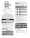
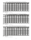
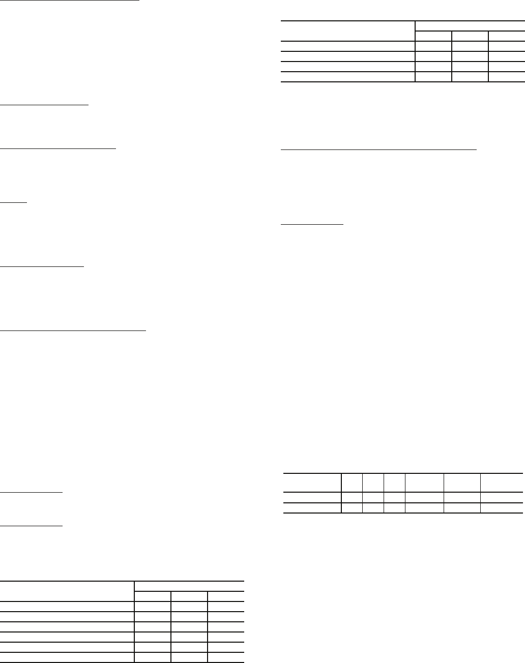
Table 16 — Humidistat/Dehumidistat Logic and
Deluxe D DIP Switch Settings
Table 17 shows the relationship between thermostat input
signals and unit operation. There are four operational inputs for
single-stage units and six operational inputs for dual-stage
units:
•Fan Only
• Cooling Stage 1
• Cooling Stage 2
• Heating Stage 1
• Heating Stage 2
• Reheat Mode
ACCESSORY 1
RELAY OPTIONS
DIP SWITCH POSITION
123
Cycle with Fan On On On
Digital NSB Off On On
Water Valve — Slow Opening On Off On
OAD On On Off
Reheat — Humidistat Off Off Off
Reheat — Dehumidistat Off On Off
NSB — Night Setback
OAD — Outside Air Damper
ACCESSORY 2
RELAY OPTIONS
DIP SWITCH POSITION
456
Cycle with Compressor On On On
Digital NSB Off On On
Water Valve — Slow Opening On Off On
OAD On On Off
NSB — Night Setback
OAD — Outside Air Damper
Sensor 2.1
2.2 2.3 Logic
Reheat
(ON) - H
Reheat
(OFF) - H
Humidistat
Off Off Off Reverse 0 VAC 24 VAC
Dehumidistat Off On Off Standard 24 VAC 0 VAC