


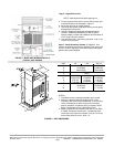
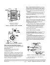
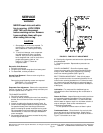
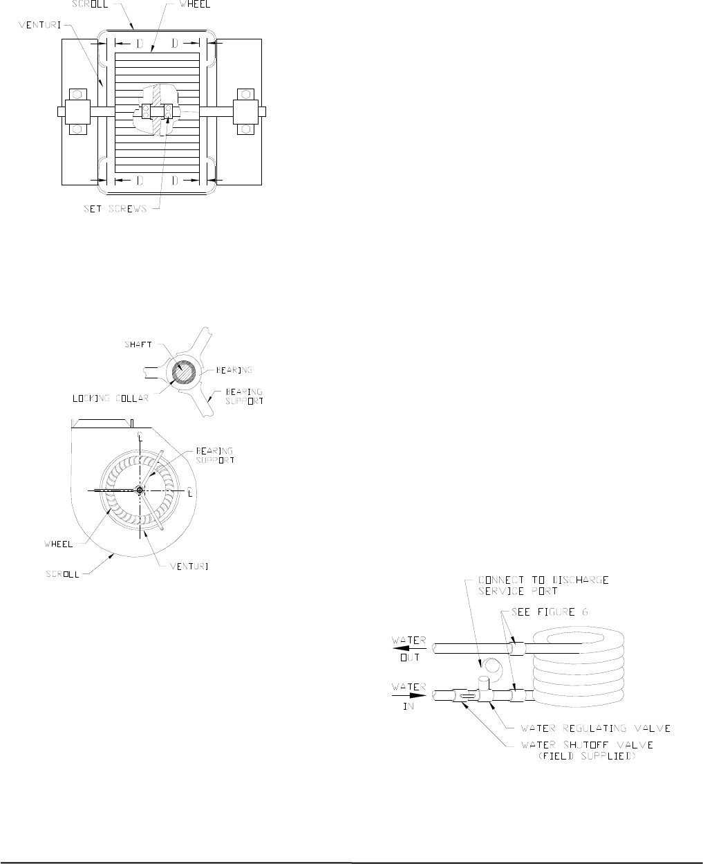
DIMENSION “D” MUST BE
EQUAL ALL AROUND
FIGURE 3 - HORIZONTAL WHEEL CENTERING
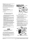
FIGURE 4 - CONCENTRIC WHEEL ALIGNMENT
Step 6 – Check Fan Shaft and Wheel Alignment-
HORIZONTAL WHEEL CENTERING - All wheels must be
horizontally centered between the inside edges of their fan
scroll ventures (Figure. 3).
Adjust as follows:
a. Loosen set screws holding wheel to shaft.
b. Center the wheel by sliding it horizontally.
c. Re-tighten set screws.
CONCENTRIC ALIGNMENT - Shaft and wheels must be
concentrically centered with the venturi (Figure. 4). Shaft
bearings are supported by bearing supports. If shaft and
wheels are concentrically misaligned from shipping shock,
it is possible to re-bend bearing support arms to original
positions. Replace the bearing support if it has been
extensively damaged during shipping.
Step 7 - Install Ventilation-Air Ductwork (If required)-
Connect ventilation ducts to flanges on outside-air supply
opening (Figure. 2) using a flexible connection. Attach
ductwork to ship structure, insulate and cover with vapor
barrier to reduce sound transmission and prevent vapor
condensation.
Weatherproof external ductwork, joints, and openings
in accordance with applicable codes. Ducts passing
through an unconditioned space must be insulated and
covered with a vapor barrier.
Step 8 - Check Return-Air Filters - Ensure filters shipped
with unit are in place. Never operate unit without return air
filters in place.
Step 9 - Check Compressor Spring Mounts (*08 & *12
size only) - The compressors are held rigid in shipment by
bolts extending through a washer, grommet and
compressor foot into a weld nut.
Loosen each bolt (4 per compressor) until compressor
floats freely on springs. Then re-tighten bolts until there is
slight pressure on the neoprene gasket. This will steady
the compressor and prevent start and stop rocking.
The compressors have reversible oil pumps that
operate in either direction; therefore, the direction of
rotation need not be checked.
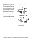
Step 10 - Make Condenser Connections
UNIT MOUNTED 90MA UNITS- Piping arrangements for
condenser cooling water are shown in Figure. 5.
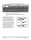
Condensers have water inlet and outlet connections as
shown in Figure 6.
Connect condenser water supply and return lines as
indicated. When connecting water lines, hold the
condenser inlet and outlet stubs firmly with a wrench at the
female pipe thread hex fitting to prevent twisting. Do not
use water lines smaller than connection sizes shown in
Figure 6. Observe all applicable plumbing and sanitary
codes.
FIGURE 5 - TYPICAL CONDENSER WATER PIPING
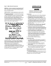
Install water-regulating valve in water supply line
outside cabinet as follows.
Manufacturer reserves the right to discontinue, or change at any time, specifications or designs without notice and without incurring obligations
Printed in U.S.A. 90MA-3SI SUPERCEDES FORM 62-02971-00 09-2009
Pg 9