


Step 12 - Make Electrical Connections
GENERAL - Provide an adequate fused disconnect switch
within sight of the unit. Provision for locking switch open
(OFF) is advisable to prevent power from being turned on
when unit is being serviced.
POWER WIRING - Conduit opening for all units is on left
side of unit near control box. Connect field power wires at
the compressor contactor.
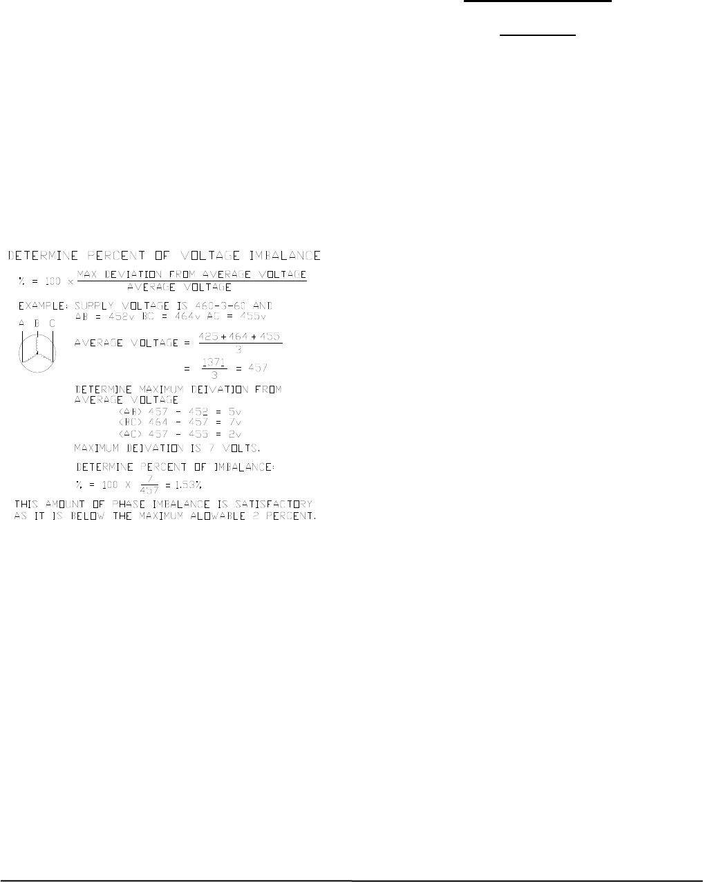
Supply voltage must be in accordance with nameplate
voltage. Voltage between phases must be balanced within
2% and current within 10% with compressor running.
Correct improper voltage or phase imbalance. Unit failure
as a result of operation on improper line voltage or
excessive phase imbalance constitutes abuse and shall
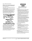
void the Carrier warranty. Use the following formula to
determine the percent voltage imbalance.
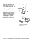
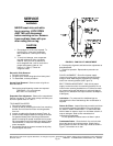
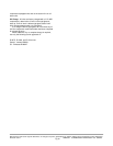
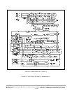
CONTROL WIRING - On extended voltage (208/230-v)
units, the control transformer is factory wired for 208-v
usage. If unit is to be used on 230-v system, reconnect
primary wiring on transformer. See Figure 12
(90MA*04/*06) or figure 14 (90MA*08/*12).
On all units, the thermostat is factory installed. A
sensing element is provided in the return air. To wire these
units to a remote thermostat, or to a remote control switch
and thermostat, refer to unit Wiring Diagram or contact
your Carrier Transicold representative.
OPERATION
CAUTION
Compressor crankcase heater must be
energized for 24 hours prior to startup to
prevent compressor bearing damage.
To start unit:
1. Thoroughly inspect exterior of unit. Clean and dust up
debris, then wash with mild soap and water solution.
2. On 90MA*08 &*12 units, ensure compressor
discharge, suction and liquid service valves are open.
(Refer to “Operation - Service Valves.) Check oil level
in compressor sight glass. If level is below glass, add
oil to bring level to approximately 1/4 glass. If level is
above bottom of glass, do not remove any oil until the
crankcase heater has been energized for at least
twenty-four hours.
3. With selector switch in OFF position, turn main power
on. Leave power on for 24 hours so that crankcase
heater can drive off accumulated refrigerant.
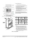
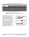
4. If desired, the selector switch may be placed in the
FAN position during the crankcase warm-up period. On
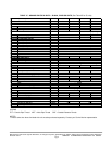
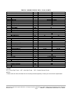
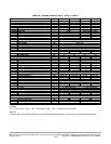
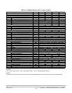
first start-up, check fan speed (Tables 1A/B/C/2A/B/C)
and rotation (Figure 1). If fan requires adjustment, refer
to “Service, Evaporator-Fan Adjustment”.
5. Allow crankcase heater to remain energized (unit
power on) for at least 24 hours. Open any valves in
condenser cooling water supply lines and then set
selector switch at COOL position. If room temperature
is above thermostat setting compressor will start. On
first start-up, set water regulating valve. (Refer to
“Service, Water Regulating Valve.)
6. Set thermostat for comfort as desired.
To Shut Down Unit:
1. Turn selector switch to OFF position. Do not shut off
main power except to service unit. The crankcase
heater is operative only when main power is on. (Refer
to “Service, Crankcase Heater”).
2. If unit is to be used for winter heating, set selector
switch at HEAT position and re-set thermostat at
desired setting.
3. If unit may be exposed to freezing temperatures, drain
water from condenser and water piping. Add a non-
corrosive antifreeze to residual water in system.
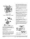
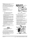
Service Valves - Always ensure that compressor suction,
and discharge service valves and liquid service valve are
open before operating unit.
The valves are accessible from the front of the unit. To
open valve, turn counterclockwise. After opening, replace
and tighten valve cap to prevent leakage.
Manufacturer reserves the right to discontinue, or change at any time, specifications or designs without notice and without incurring obligations
Printed in U.S.A. 90MA-3SI SUPERCEDES FORM 62-02971-00 09-2009
Pg 12