


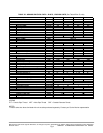
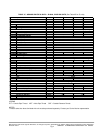
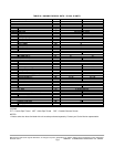
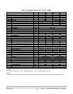
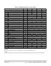
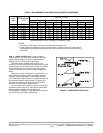
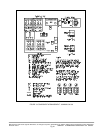
TABLE 3 - RECOMMENDED LINE SIZES (INCHES) REMOTE CONDENSERS
DISCH LIQUID DISCH LIQUID DISCH LIQUID DISCH LIQUID
404 R-407C 1/2 3/8 5/8 3/8 5/8 3/8 5/8 3/8
406 R-407C 5/8 3/8 3/4 3/8 3/4 3/8 3/4 3/8
408 R-407C 3/4 1/2 3/4 1/2 7/8 1/2 7/8 1/2
412 R-407C 7/8 1/2 7/8 1/2 7/8 1/2 1-1/8 5/8
504 R-404A 5/8 3/8 5/8 3/8 3/4 3/8 3/4 3/8
506 R-404A 3/4 1/2 3/4 1/2 7/8 1/2 7/8 1/2
508 R-404A 7/8 1/2 7/8 1/2 1-1/8 1/2 1-1/8 5/8
512 R-404A 7/8 5/8 1-1/8 5/8 1-1/8 5/8 1-1/8 5/8
* Recommended line sizes correspond to 2 degree F drop.
LENGTH OF RUN
UNIT
90MU
REFRIGERANT
TYPE
76-10051-7526-500-25
NOTES:
1. Pipe sizes should never be smaller than cooling unit connection size.
2. Table is based on 2 degree F drop over entire length. Excessive (more than a few) elbows
and fittings will significantly affect pressure drop. If this situation exists, line sizing must be re-
calculated.
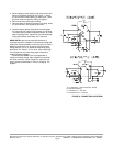
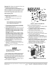
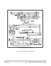
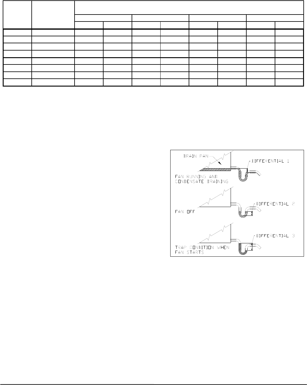
Step 11 - Install Unit Drain Line - Install a trapped
condensate drain line at unit drain connection The drain
requires standard pipe connected to condensate pan
nipple(s). Figure 7 shows proper trap design.
Determine design negative static pressure. This
pressure is not the same as fan total static pressure, which
includes pressure losses downstream as well as upstream
from the evaporator air fan. Always assume the worst
conditions, such as having return air filters clogged with
debris.
Referring to Figure 7, differential 1 must be equal to or
larger than negative static pressure at design operating
condition. Store enough water in trap to prevent losing
seal. Differential 2 must be equal to or larger than one-half
the maximum negative static pressure. To avoid loss of
seal when the fan starts, differential 3 must be greater
than the maximum negative static pressure.
Do not use drain line smaller than 3/4 inch. Use hole(s)
provided in panel for drain line. Pitch drain line downward
toward scupper. Installation of a plugged tee is
recommended for cleaning. Fill trap with water to make an
air seal. Observe all sanitary requirements.
FIGURE 7 - CONDENSATE DRAIN TRAP
Manufacturer reserves the right to discontinue, or change at any time, specifications or designs without notice and without incurring obligations
Printed in U.S.A. 90MA-3SI SUPERCEDES FORM 62-02971-00 09-2009
Pg 11