


8
PAM
RTV
A93087
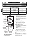
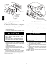
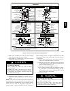
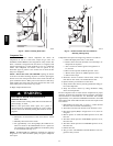
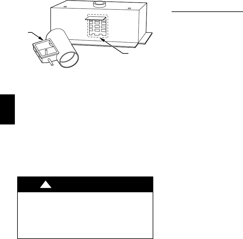
Fig. 9 -- Combustion--Air Intake Housing
Gasket Repair
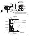
13. Refer to furnace wiring diagram and reconnect wires to
flame rollout switch, gas valve, igniter, and flame sensor.
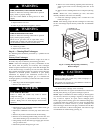
14. Reconnect pressure switch tubes to gas valve and intake
housing. Refer to tube routing label on main furnace door
for proper tube location. (See Fig. 10.) Be sure tubes are not
kinked.
15. Turn on gas and electrical supplies to furnace.
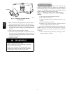
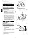
16. Check furnace operation through two complete heat operat-
ing cycles. Look through sight glass in burner enclosure to
check burners. Burner flames should be clear blue, almost
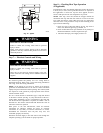
transparent. (See Fig. 11.)
17. Check for gas leaks.
FIRE OR EXPLOSION HAZARD
Failure to follow this warning could result in personal
injury, death or property damage.
Never test for gas leaks with an open flame. Use a
commercially available soap solution made specifically
for the detection of leaks to check all connections.
!
WARNING
18. Replace main furnace door.
Secondary Heat Exchangers
NOTE: The condensing side (inside) of the secondary heat
exchangers CANNOT be serviced or inspected. A small number of
bottom outlet openings can be inspected by removing the inducer
assembly. See Flushing Collector Box and Drainage System
section for details on removing inducer assembly.
Step 5 — Flushing Collector Box and Drainage
System
1. Turn off gas and electrical supplies to furnace.
2. Remove main furnace door.
3. Disconnect inducer motor and pressure switch wires or con-
nectors.
4. Disconnect pressure switch tubes.
5. Disconnect vent pipe from inducer housing outlet by
loosening coupling clamp on inducer outlet.
6. Disconnect drain tube from inducer housing. (See Fig. 10.)
NOTE: Ensure the drain tube disconnected from the inducer
housing is higher than the collector box opening or water will flow
out of tube.
7. Remove inducer housing assembly by removing 4 bolts at-
taching assembly to cell panel.
58MCB