


14
A99118
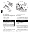
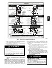
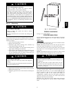
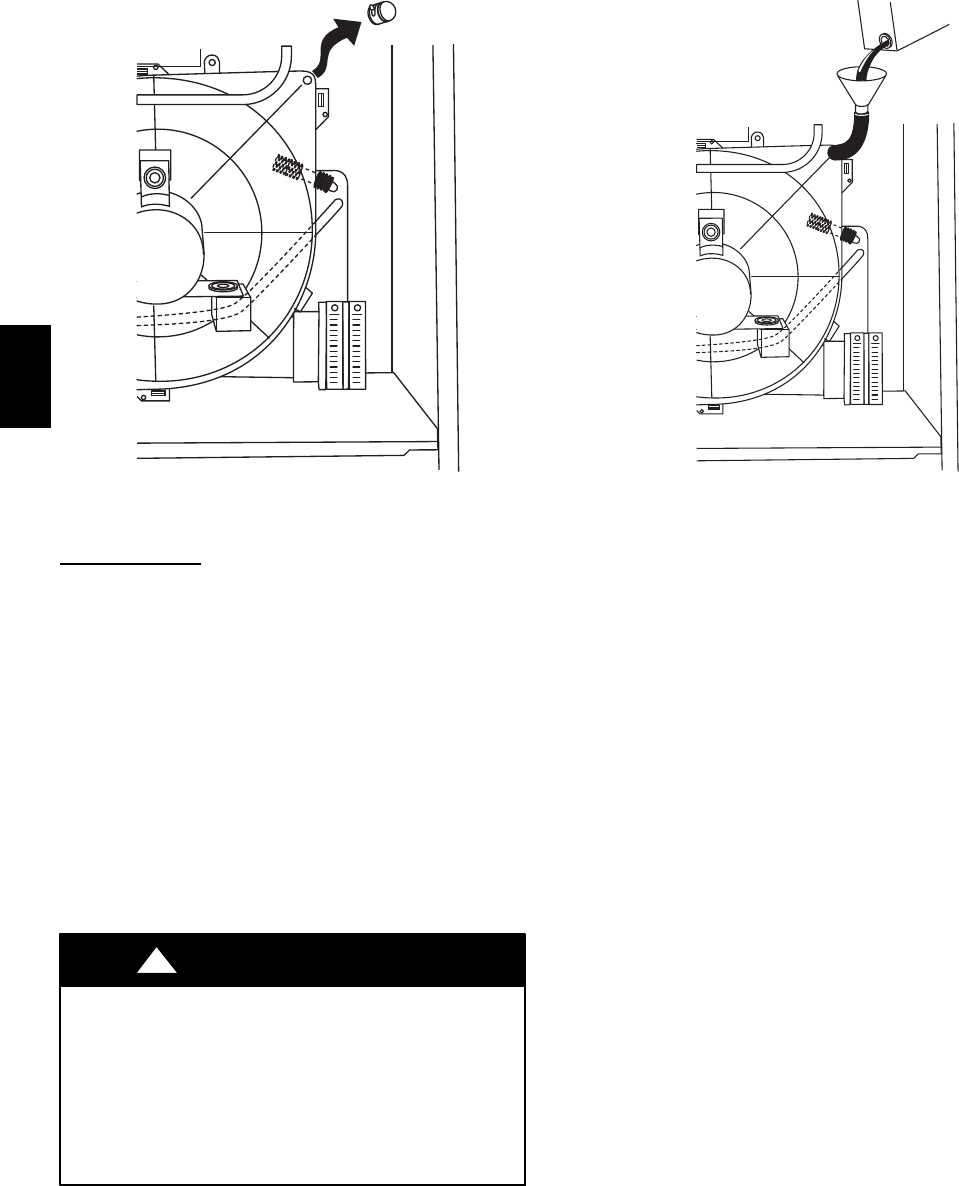
Fig. 18 -- Inducer Housing Drain Tube
Component Test
NOTE: The furnace control component test allows all
components to run for a short time; except the gas valve and
humidifier terminal HUM are not energized for safety reasons. The
EAC--1 terminal is energized when the blower is energized. This
feature helps diagnose a system problem in case of a component
failure. The component test feature will not operate if any
thermostat signal is present at the control and not until all time
delays are completed.
NOTE: Record the status code BEFORE opening the blower
access door and before shutting off power to furnace. Opening the
blower access door will open the blower door switch and shut off
power within the furnace. When power to the furnace is shut off by
either method, the status code will be lost because the code is not
stored while power is removed for any reason.
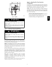
To Begin Component Self--Test:
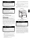
ELECTRICAL SHOCK AND UNIT MAY NOT
OPERATE HAZARD
Failure to follow this warning could result in electrical shock,
personal injury, or death.
Blower access panel door switch opens 115--v power to
control board. No component operation can occur. Caution
must be taken when manually closing this switch for service
purposes.
!
WARNING
1. Remove blower access door.
2. Disconnect the thermostat R lead from furnace control
board.
3. Manually close blower door switch.
4. For approximately 2 sec, short (jumper) the COM--24v ter-
minal on control to the TEST/TWIN 3/16--in. quick--con-
nect terminal on control until LED turns off. Remove jump-
er from terminals. (See Fig. 16.)
NOTE: If TEST/TWIN and COM--24v terminals are jumpered
longer than 2 sec, LED will flash rapidly and ignore component
test request.
A99119
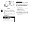
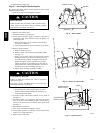
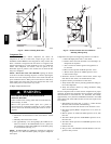
Fig. 19 -- Funnel in Drain Tube and Antifreeze
Running Through Trap
Component test sequence for single--stage furnace is as follows:
a. LED will display status code 11 four times.
b. Inducer motor starts and continues to run until Step f. of
component test sequence.
c. After 7 sec the hot surface igniter is energized for 15
sec, then off.
d. Blower motor operates on HEAT speed for 10 sec.
e. Blower motor operates on COOL speed for 10 sec.
f. Inducer motor stops.
5. Reconnect R lead to furnace control board, remove tape
from blower door switch, and reinstall blower door.
6. Operate furnace per instruction on outer door.
7. Verify furnace shut down by lowering thermostat setting be-
low room temperature.
8. Verify that furnace restarts by raising thermostat setting
above room temperature.
Use the Component Test to check furnace components for proper
operation. To initiate the component self--test sequence, shut off the
room thermostat or disconnect the “R” thermostat lead. Briefly
(approximately 2 sec) short the TWIN/TEST terminal to the COM
24V terminal. The status LED will turn off. The test sequence will
be as follows:
1. LED flashes last status code, or code 11, 4 times. Record
this status code for further troubleshooting.
2. The inducer will start and continue to run until test is over.
3. Hot surface igniter (HSI) is energized for 15 sec, then de--
energized.
4. Blower operates on continuous FAN speed for 10 sec, then
turns off.
5. The blower motor operates on HEATING speed for 10 sec,
then turns off.
6. The blower motor operates on COOLING speed for 10 sec,
then turns off.
7. Inducer turns off.
8. The gas valve and humidifier terminal HUM are not ener-
gized for safety reasons.
58MCB