


4
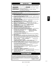
Table 1 – Furnace Air Filter Table
FURNACE CASING WIDTH
IN (MM)
FILTER QUANTITY AND SIZE *
FILTER TYPE*SIDE RETURN*
IN (MM)
BOTTOM RETURN*
IN (MM)
17---1/2 (445)
(1) 16 x 25 x 3/4
(406 x 635 x 19)
(1) 16 x 25 x 3/4
(406 x 635 x 19)
3/4” (19 mm ) thick washable
21 (533 )
(1) 16 x 25 x 3/4
(406 x 635 x 19)
(1) 20 x 25 x 3/4
(508 x 635 x 19)
3/4” (19 mm ) thick washable
24---1/2 (610)
(1) 16 x 25 x 3/4
(406 x 635 x 19)
(1) 24 x 25 x 3/4
(610 x 635 x 19)
3/4” (19 mm ) thick washable
Table 2 – Air Filter Located in Filter Cabinet
FILTER CABINET HEIGHT --- IN (MM) F ILT ER S IZE --- I N (MM ) FILTER TYPE
16 (406)
(1) 16 x 25 x 3/4*
(406 x 635 x 19) or
(1) 16 x 25 x 4---5/16
(406 x 635 x 110)
washable
20 (508)
(1) 20 x 25 x 3/4*
(508 x 635 x 19) or
(1) 20 x 25 x 4---5/16
(508 x 635 x 110)
washable
24 (610)
(1) 24 x 25 x 3/4*or
(610 x 635 x 19) or
(1) 24 x 25 x 4---5/16
(610 x 635 x 110)
washable
* Filters with a side return--air may have a different filter size. Measure the filter to obtain the correct size.
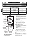
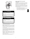
COLLECTOR BOX
TUBE (PINK)
COLLECTOR BOX
TUBE (GREEN)
INDUCER HOUSING
(MOLDED) DRAIN
TUBE (BEHIND
COLLECTOR BOX
DRAIN TUBE)
COLLECTOR BOX
DRAIN TUBE (BLUE)
FIELD-INSTALLED
FACTORY-SUPPLIED
DRAIN TUBE
COUPLING (LEFT
DRAIN OPTION)
FIELD-INSTALLED
FACTORY-SUPPLIED
DRAIN TUBE
FIELD-INSTALLED
FACTORY-SUPPLIED
1
⁄
2
-IN. CPVC STREET
ELBOWS (2) FOR
LEFT DRAIN OPTION
FIELD-INSTALLED
FACTORY-SUPPLIED
DRAIN TUBE
COUPLING (RIGHT
DRAIN OPTION)
CAP
COLLECTOR BOX
DRAIN TUBE (BLUE
& WHITE STRIPED)
PLUG
CONDENSATE
TRAP
A05110
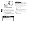
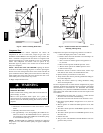
Fig. 5 -- Factory--Shipped Upflow Tube Configuration
(Shown with Blower Access Panel Removed)
1. Turn off electrical supply to furnace.
2. Remove filter cabinet door.
3. Slide filter out of cabinet.
4. If equipped with permanent, washable filter, clean filter by
spraying cold tap water through filter in opposite direction
of airflow. Rinse filter and let dry. Oiling or coating of the
filter is not recommended.
5. If equipped with factory specified disposable media filter,
replace only with a factory specified media filter of the same
size.
6. Slide filter into cabinet.
7. Replace filter cabinet door.
8. Turn on electrical supply to furnace.
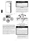
If filter is installed in furnace blower compartment:
1. Turn off electrical supply to furnace.
2. Remove main furnace door and blower access panel.
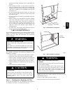
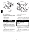
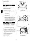
3. Release filter retainer wire. (See Fig. 3 or 4.)
NOTE: Filters shown in Fig. 3 and 4 can be in furnace blower
compartment or in filter cabinet, but not in both.
4. Slide filter out of furnace.
5. If furnaces are equipped with permanent, washable filter(s),
clean filter by spraying cold tap water through filter in op-
posite direction of airflow.
6. Rinse filter and let dry. Oiling or coating filter is not recom-
mended.
7. Slide filter into furnace.
8. Recapture filter retaining wire.
9. Replace blower access panel and main furnace door.
10. Turn on electrical supply to furnace.
Step 2 — Blower Motor and Wheel Maintenance
To ensure long life, economy, and high efficiency, clean
accumulated dirt and grease from blower wheel and motor
annually.
The inducer and blower motors are pre--lubricated and require no
additional lubrication. These motors can be identified by the
absence of oil ports on each end of the motor.
The following items should be performed by a qualified service
technician.
Clean blower motor and wheel as follows:
58MCB