


9. Mark blower wheel, motor, and motor support in relation to
blower housing before disassembly to ensure proper reassem-
bly.
10. Loosen setscrew holding blower wheel on motor shaft.
11. Remove bolts holding motor mount to blower housing and
slide motor and mount out of housing. Disconnect ground wire
attached to blower housing before removing motor.
12. Lubricate motor (when oil ports are provided).
a. Remove dust caps or plugs from oil ports located at each
end of motor.
b. Use a good grade of SAE 20 nondetergent motor oil and
put 1 teaspoon, 5 cc, 3/16 oz, or 16 to 25 drops in each oil
port. Do not over-oil.
c. Allow time for total quantity of oil to be absorbed by each
bearing.
d. Wipe excess oil from motor housing.
e. Replace dust caps or plugs on oil ports.
13. Remove blower wheel from housing.
a. Mark cutoff location to ensure proper reassembly.
b. Remove screws holding cutoff plate and remove cutoff
plate from housing.
c. Lift blower wheel from housing through opening.
14. Clean blower wheel and motor using a vacuum cleaner with
soft brush attachment. Do not remove or disturb balance
weights (clips) on blower wheel blades. The blower wheel
should not be dropped or bent as balance will be affected.
15. Reinstall blower wheel by reversing steps 13 a. through c. Be
sure wheel is positioned for proper rotation.
16. Reassemble motor and blower by reversing steps 5 through
11. If motor has ground wire, be sure it is connected as before.
Be sure the motor is properly positioned in the blower
housing. The motor oil ports must be at a minimum of 45°
above the horizontal centerline of the motor after the blower
assembly has been reinstalled in the furnace.
17. Reinstall blower assembly in furnace. Connect electrical leads
to blower speed selector. Connections are polarized for
assembly. DO NOT FORCE.
18. Reinstall control box.
19. Reconnect wires to auxiliary limit switch on blower housing
(downflow furnace only).
20. Reinstall vent pipe and enclosure (downflow furnaces only).
21. Turn on electrical power and check for proper rotation and
speed changes between heating and cooling.
22. Replace blower access door and secure with 2 screws (down-
flow furnace only).
CLEANING HEAT EXCHANGER
The following steps should be performed by a qualified service
technician:
NOTE: Deposits of soot and carbon indicate the existence of a
problem which needs to be corrected. Take action to correct the
problem.
If it becomes necessary to clean the heat exchanger because of
carbon deposits, soot, etc., proceed as follows:
1. Turn off gas and power to furnace.
2. Remove 2 screws from blower access door (downflow furnace
only). Remove control and blower access doors.
3. Remove vent pipe enclosure (downflow furnace only) and
disconnect vent pipe from relief box.
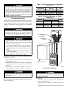
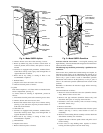
4. Remove 2 screws that secure relief box. (See Fig. 4 or 5.)
5. Disconnect wires to the following components:
a. Draft safeguard switch
b. Inducer motor
c. Pressure switch
d. Limit overtemperature switch
e. Gas valve
f. Edge connector leading to control box
6. Remove 8 screws that secure flue collector box to center
panel. Be careful not to damage sealant.
7. Remove complete inducer assembly from furnace, exposing
flue openings.
8. Clean cells as follows using field-provided small wire brush,
steel spring cable, reversible electric drill, and vacuum
cleaner.
a. Assemble wire brush and steel spring cable.
(1.) Use 48 in. of 1/4-in. diameter high-grade steel spring
cable (commonly known as drain clean-out or Roto-
Rooter cable).
(2.) Use 1/4-in. diameter wire brush (commonly known as
25-caliber rifle cleaning brush).
NOTE: The items needed in steps (1.) and (2.) can usually be
purchased at local hardware stores.
(3.) Insert twisted wire end of brush into end of steel spring
cable, and crimp tight with crimping tool or strike with
ball-peen hammer. TIGHTNESS is very important.
(4.) Remove metal screw fitting from wire brush to allow
insertion into cable.
b. Clean each heat exchanger cell.
(1.) Attach variable-speed, reversible drill to end of steel
spring cable (end opposite brush).
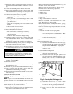
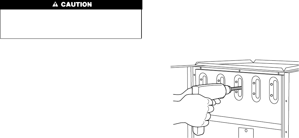
(2.) Insert brush end of cable into upper opening of cell
and slowly rotate with drill. DO NOT force cable.
Gradually insert at least 36 in. of cable into 2 upper
passes of cell. (See Fig. 6.)
(3.) Work cable in and out of cell 3 or 4 times to obtain
sufficient cleaning. DO NOT pull cable with great
force. Reverse drill and gradually work cable out.
(4.) Remove burner assembly and cell inlet plates.
(5.) Replace screws in center panel and cells before
cleaning.
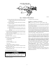
Fig. 6—Cleaning Heat Exchanger Cell
A91252
4