


(6.) Insert brush end of cable in lower opening of cell, and
proceed to clean 2 lower passes of cell in same manner
as 2 upper passes.
(7.) Repeat foregoing procedures until each cell in furnace
has been cleaned.
(8.) Remove residue from each cell using vacuum cleaner.
(9.) Clean burner assembly using vacuum cleaner with soft
brush attachment.
(10.) Reinstall cell inlet plates and burner assembly. Care
must be exercised to center the burners in the cell
openings.
9. After cleaning flue openings, check sealant on flue collector to
ensure that it has not been damaged. If new sealant is needed,
contact your dealer or distributor.
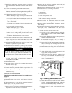
10. Clean and replace flue collector assembly, making sure all 8
screws are secure.
11. Reinstall 2 screws in relief box.
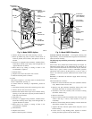
12. Reconnect wires to the following components:
a. Draft safeguard switch
b. Inducer motor
c. Pressure switch
d. Limit overtemperature switch
e. Gas valve
f. Edge connector leading to control box
13. Reconnect vent pipe to relief box. Replace vent pipe enclosure
(downflow furnace only).
14. Replace blower access door only and secure with 2 screws
(downflow furnace only).
15. Turn on electrical power and gas.
16. Set thermostat and check furnace for proper operation.
Never use a match or other open flame to check for gas leaks.
Use a soap-and-water solution. A failure to follow this
warning could result in fire, personal injury, or death.
17. Check for gas leaks.
18. Replace control access door.
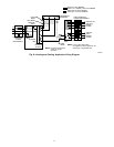
ELECTRICAL CONTROLS AND WIRING
NOTE: There may be more than 1 electrical supply to unit.
The electrical ground for 115-v wiring must be maintained
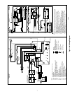
properly. Refer to Fig. 8 for field wiring information and to Fig. 9
for unit wiring information.
With power disconnected to unit, check all electrical connections
for tightness. Tighten all screws on electrical connections. If any
smoky or burned connections are noticed, disassemble the connec-
tion, clean all parts and stripped wire, and reassemble properly and
securely. Electrical controls are difficult to check without proper
instrumentation; therefore, reconnect electrical power to unit and
observe unit through 1 complete operating cycle.
The 24-v circuit contains an automotive-type, 3-amp fuse located
on the main control board. Any direct shorts during installation,
service, or maintenance could cause this fuse to blow. If fuse
replacement is required, use ONLY a 3-amp fuse of identical size.
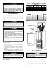
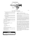
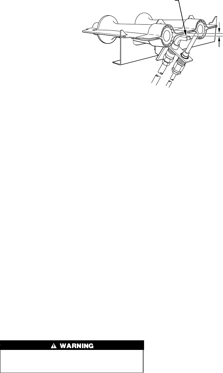
PILOT — Check the pilot and clean if necessary at the beginning
of each heating season. The pilot flame should be high enough for
proper impingement of the flame-sensing element (or thermo-
couple) and to light the burners. Remove the accumulation of soot
and carbon from the flame-sensing element (or thermocouple).
Refer to Fig. 7 for proper location of pilot on burner assembly.
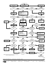
TROUBLESHOOTING — Page 8 contains a troubleshooting
chart. This chart can be a useful tool in isolating furnace operation
problems. Beginning with the word ‘‘Start,’’ answer each question
and follow the appropriate arrow to the next item.
The chart will help identify the problem or failed component. After
replacing any component, verify correct operating sequence as
indicated by bold arrows.
Fig. 7—Position of Pilot to Burner
A91249
1
/
8
″
PILOT HEAD V–NOTCH FALLS
DIRECTLY BELOW FRONT EDGE
OF BURNER CARRYOVER.
5