


b. Remove blower access door after removing 2 screws.
c. Reach up behind top plate, tilt filters toward center of
return-air plenum, remove filters, and replace or clean as
needed.
d. Furnaces are equipped with permanent, washable filters.
Clean filters with tap water. Spray water through filter in
opposite direction of airflow.
e. Rinse and let dry. Oiling or coating of filters is not
recommended or required.
f. Reinstall filters.
g. Replace access door and secure with 2 screws.
h. Restore electrical power to furnace.
2. Upflow
Each furnace requires 1 or 2 filters which are installed in the
blower compartment. (See Fig. 4.)
To remove filters for cleaning or replacement, proceed as
follows:
a. Disconnect electrical power before removing access doors.
b. Remove blower and control access doors.
c. Release filter retainer from clip at front of furnace casing.
(See Fig. 4.) For side return, clips may be used on either or
both sides of the furnace.
d. Slide filter out.
e. Furnaces are equipped with permanent, washable filters.
Clean filter with tap water. Spray water through filter in
opposite direction of airflow.
f. Rinse and let dry. Oiling or coating of filter is not
recommended or required.
g. Reinstall filter.
h. Replace access doors.
i. Restore electrical power to furnace.
BLOWER MOTOR AND WHEEL — For long life, economy, and
high efficiency, clean accumulated dirt and grease from the blower
wheel and motor annually.
The following steps should be performed by a qualified service
technician:
Some motors have prelubricated sealed bearings and require no
lubrication. These motors can be identified by the absence of oil
ports on each end of the motor. For motors with oil ports, lubricate
motor every 5 years if motor is used on intermittent operation
(thermostat FAN switch in AUTO position), or every 2 years if
motor is in continuous operation (thermostat FAN switch in ON
position).
Remember to disconnect the electrical supply before removing
access doors.
Clean and lubricate as follows:
1. Remove 2 screws from blower access door (downflow furnace
only). Remove blower access door.
2. Remove vent pipe enclosure (downflow furnace only) and
disconnect short piece of vent pipe from relief box.
3. Disconnect wires from auxiliary limit on blower housing
(downflow furnace only).
4. Remove control box.
5. Remove electrical leads from numbered side of blower speed
selector. (See Fig. 4 and 5.) Note location of wires for
reassembly.
6. Remove screws holding blower assembly to blower deck and
slide blower assembly out of furnace.
7. Squeeze side tabs of blower speed selector and pull it out of
blower housing.
8. Loosen screw in strap holding motor capacitor to blower
housing and slide capacitor out from under strap.
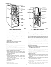
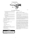
Fig. 4—Model 58GFA Upflow
A92178
DRAFT
SAFEGUARD
SWITCH
RELIEF
BOX
MOUNTING
SCREWS
FLUE
COLLECTOR
BOX
GAS
VALVE
PILOT
SPEED
SELECTOR
FILTER
RETAINER
WASHABLE
FILTER
CONTROL
BOX
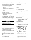
Fig. 5—Model 58DFA Downflow
A92179
VENT PIPE
ENCLOSURE
CONTROL
BOX
DRAFT
SAFEGUARD
SWITCH
FLUE
COLLECTOR
BOX
AUXILIARY
LIMIT SWITCH
(NOT VISIBLE)
SPEED
SELECTOR
MOUNTING
SCREWS
RELIEF
BOX
3